


22 en | Connections Dinion IP
V 2.5 | 2007.6 Operating Instructions Bosch Security Systems
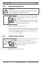
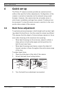
2.2 Network (and power)
Fig. 2.2 Network and power connection
The multicolored LED under the Ethernet connection indicates
Power (red), IP connection (green) and IP traffic (green flash-
ing). It can be disabled in the Settings/Camera Settings/
Installer options menu.
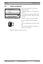
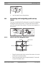
2.3 Video service monitor
Fig. 2.3 Service monitor connection
!
CAUTION!
Never supply power via the Ethernet connection (PoE) when
power is supplied via the power connector.
VIDEO
DC
1
2
V
AC
24
V
ALARM
ETH
UTP Cat 5 RJ45
- connect the camera to a 10/100 Base-T network.
- use a shielded UTP Category 5 cable with RJ45
connectors.
- Power can be supplied to the camera via the Eth-
ernet cable compliant with the Power-over-Ether-
net (IEEE 802.3af) standard.
VIDEO
DC 12V
AC 24V
ALAR
M
ETH
- connect a service monitor to the composite video
BNC connector to aid installation.
- a monitor connected close to the camera via this
connection can also be used in parallel with
remote PC viewing.