


Dinion IP Connections | en 23
Bosch Security Systems Operating Instructions V 2.5 | 2007.6
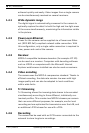
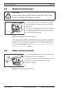
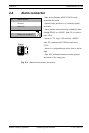
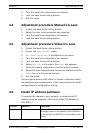
2.4 Alarm connector
Fig. 2.4 Network and power connection
Alarm
Pin 1
Pin 4
Pin Alarm socket
1Ground
2 Alarm in
3 Relay out contact 1
4 Relay out contact 2
- Max. wire diameter AWG 22-28 for both
stranded and solid.
- Default relay position n.o. (normally open),
no alarm.
- Alarm output relay switching capability: Max
voltage 30VAC or +40VDC. Max 0.5 A continu-
ous, 10VA.
- Alarm in: TTL logic, +5V nominal, +40VDC
max, DC coupled with 22kOhm pull-up to
+3.3V.
- Alarm in: configurable as active low or active
high.
- Max. 42V allowed between camera ground
and each of the relay pins.