


Dinion IP Operation via the browser | en 35
Bosch Security Systems Operating Instructions V 2.5 | 2007.6
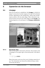
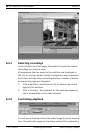
6.1.2 Image selection
You can view the image on a full screen.
– Click one of the MPEG-4 Stream 1, MPEG-4 Stream 2 or M-
JPEG tabs below the video image to switch between the
different displays for the camera image.
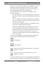
6.1.3 Digital I/O
Depending on the configuration of the unit, the alarm input and
the relay output are displayed next to the camera image. The
alarm symbol is for information and indicates the input status
of the alarm input: Active 1 = Symbol is green, Active 0 = Sym-
bol not lit. The relay on the camera allows you to operate a
device (for example a light or a door opener).
– To operate, click the relay symbol next to the video image.
The symbol is red when the relay is activated.
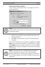
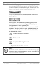
6.1.4 System log / Event log
The System log field contains information about the operating
status of the camera and the connection. These messages can
be saved automatically in a file. Events such as the triggering or
end of alarms are shown in the Event log field. These messages
can be saved automatically in a file.
6.1.5 Saving snapshots
Individual images from the video sequence that is currently
being shown on the Livepage can be saved in JPEG format on
the computer's hard drive.