


Chapter 2 Setting Up and Configuring the Multi Services Platform
Mounting the Multi Services Platform in a Rack
2-8
Cisco Video Surveillance Manager Getting Started Guide, Release 4.2/6.2
OL-19733-01
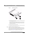
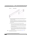
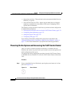
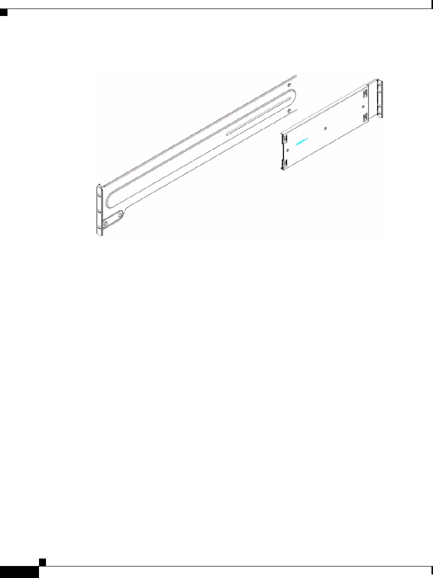
Figure 2-2 Outer Rack Rails
a. Make sure that the right short and long outer rack rail brackets are connected
to each other and that the left short and long outer rack rail brackets are
connected to each other.
The brackets are marked R and L. To connect the brackets, align the pin on
the small bracket with the slot on the corresponding large bracket, align the
two pins on the large bracket with the slots on the small bracket, and slide the
brackets together.
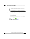
b. Attach the outer rack rails to the rack, following these guidelines:
–
The outer rack rail marked R attaches to the right of the rack as you face
the front of the rack. The one marked L attaches to the left of the rack.
–
The long outer bracket faces the front of the rack and the short bracket
faces the rear of the rack.
–
The bracket flanges overlap the outer edge of the rack mounting rail.
–
Secure the long bracket to the front of the rack with two 1/2 inch (12.7
mm) screws, and secure the short bracket to the rear of the rack with three
1/2 inch (12.7 mm) screws. The screws are provide with your Multi
Services Platform.
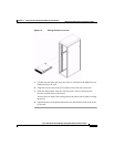
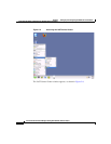
Step 3 Place the Multi Services Platform in a rack by referring to Figure 2-3 and
performing the actions that follow.