


M3099EX/EH OEM Manual 3-93
INTERFACE
SPECIFICATIONS
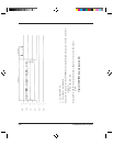
Command/
Response Timing
Chart
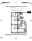
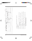
These timing charts are in the normal sequence at connector pins of
the scanner. In these charts, STB, PB and SPB mean start bit, parity
bit, and stop bit respectively.
Figure 3.10 to Figure 3.15 shows the timing chart for each
command.
Figure 3.10 CLEAR command sequence
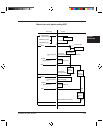
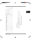
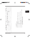
Figure 3.11 CONTROL command sequence
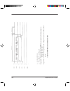
Figure 3.12 START command sequence
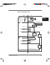
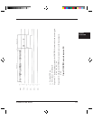
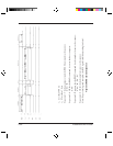
Figure 3.13 READ command sequence
Figure 3.14 SENSE command sequence
Figure 3.15 RETURN SENSE command sequence