


3-40 M3099EX/EH OEM Manual
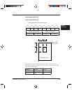
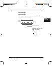
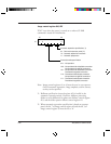
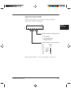
Image control register A#1, B#1
X”00" is set when the power is turned on or when a CLEAR
command is issued for initialization.
00 0
b7 b0
#1
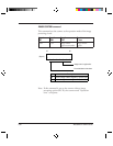
Automatic separation specification (*1)
0 x : Set from the operator panel (*2)
1 0 : Automatic separation is not done.
1 1 : Automatic speparation
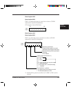
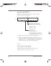
Conversion mode specification
0 x x : Not operation
1 0 0 : Not provided with white/black conversion.
Not provided with right/left conversion.
1 0 1 : Not provided with white/black conversion.
Provided with right/left conversion.
1 1 0 : Provided with white/black conversion.
Not provided with right/left conversion.
1 1 1 : Provided with white/black conversion.
Provided with right/left conversion.
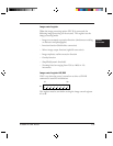
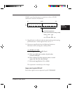
Note: Image control registers #1 to #3 must be sent in one sequence.
One of automatic separation, image emphasis, outline extract,
overlay can be specified.
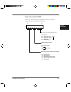
*1: Halftone specification (control register #2) is invalid in the
automatic separation mode. However, halftone processing
(dither or error diffusion) for photo area follows control register
#19, and the dither pattern follows control register #2.
*2: When automatic separation specification is based on operator
panel, the bit 7 of image control register #2 and the bit 3 of
image control register #3 must be set to '0'.