M3099EX/EH OEM Manual 1-9
OVERVIEW
Main control unit
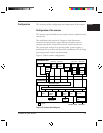
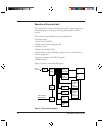
This scanner is controlled by a 80C186 MPU. This scanner consists
of a ROM as a program area, internal registers, an external RAM as a
work area, gate arrays for the MPU peripheral and video circuits,
dither processing and γ conversion RAMs, and error diffusion.
Interface control
RS-232C and video interface
RS-232C interface
The RS-232C interface consists of an ACIA( 8251) and driver-receiver
ICs (145406).
Video interface
This scanner processes a document by the 256-step gray scale. Images
are processed in a way specified by the interface or the operator panel
and transferred serially in eight-bit units. Eight-bit data has V0 at the
left end and V7 at the right end and strobed by VCL.
HGATE ensures the validity of data in the main scanning and
VGATE for the subscanning.
The scanner status is basically reported by the RS-232C interface. An
equipment error is reported to the host computer by a FAIL signal in
case that RS-232C communication failed. See Chapter 3 for detailed
specifications of the interfaces.
Resolution
The basic resolution of this scanner is 200dpi. The resolution can be
changed to 240, 300, or 400dpi from the host computer or the
operator panel.
The resolution in the subscanning direction is achieved by changing
the document transport speed.
When the image processing circuit II (IPC II) option is installed, the
linear density is changed by setting the parameter to its internal circuit.


