


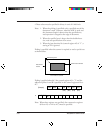

3-30 M3099EX/EH OEM Manual
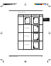
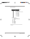
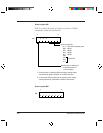
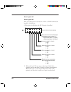
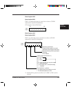
Control register A#4
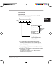
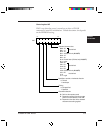
Control register B#4
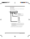
X’20' is set when power is turned on or when a CLEAR command is
issued for initialization.
• This register is valid when the IPC II option is installed.
b7 b0
Binary data when the threshold equals
video data to be binary-coded. (*1)
A#4
B#4
(Dynamic threshold mode setting)
00
0: Output binary data is "1". (Black)
1: Output binary data is "0". (White)
Noise removing of 2 × 2 matrix
0: OFF
1: ON
Noise removing of 3 × 3 matrix
0: OFF
1: ON
Noise removing of 4 × 4 matrix
0: OFF
1: ON
Noise removing of 5 × 5 matrix
0: OFF
1: ON
Enables the noise removing bits
(bits 1-4 when this bit is active).
0: ON
1: OFF
*1: When this bit is "0", the output video data is black if the
gradation of the video data is equal to or larger than threshold.
When this bit is "1", the output video data is white if the
gradation of video data is equal to or larger than threshold.