


M3099EX/EH OEM Manual 3-27
INTERFACE
SPECIFICATIONS
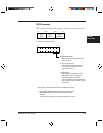
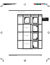
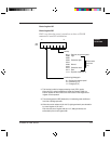
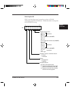
Control register A#1
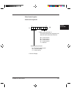
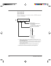
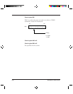
Control register B#1
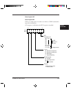
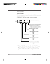
X’00' is set when the power is turned on or when a CLEAR
command is issued for initialization.
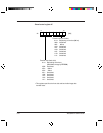
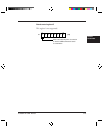
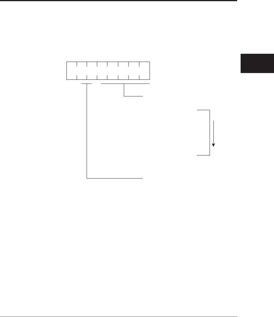
b7 b0
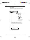
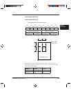
*1: This function is valid for image processing circuit (IPC II) option.
When the IPC II option is installed and these bits indicate IXXXX, the
scanner applies the DTC function, and the function of the image control
register are not operated.
*2 The scanning speed of ADF (sheets/min) in linedrawing mode is different
from that of photograph mode.
*3: When the control resister #19, bit 0 is "0", eight types density are selectable
by control register #1, bit 3 to 0.
And when the control register #19, bit 0 is "1", 256 types density are
sellectable by the control register #20.
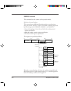
Density
00×××: Set from the operator panel
01000: Light
01001:
01010: Somewhat light
01011:
01100: Normal
01101:
01110: Somewhat dark
01111: Dark
1××××: Dynamic threshold (*1)
Linedrawing/photograph
A#1
B#1
0×: Set from the operator panel
10: Linedrawing (*2)
11: Photograph (*2)
Darken more
and more
(*3)