


1-8 M3099EX/EH OEM Manual
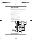
Operation of the control unit
The control unit consists of an operator panel, a power supply unit,
mechanism driver, an image processing control, and an interface
control.
This scanner has the following circuit configuration:
• Operator panel
• Control circuit (MPU)
• Video circuit (front-side/back-side)
• Interface circuit
• Duplex circuit (back-side)
• Motor driver circuit (including a stepper motor, a clutch driver)
• Power supply unit
• Image processing circuit (IPC II option)
• Memory board
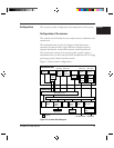
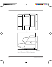
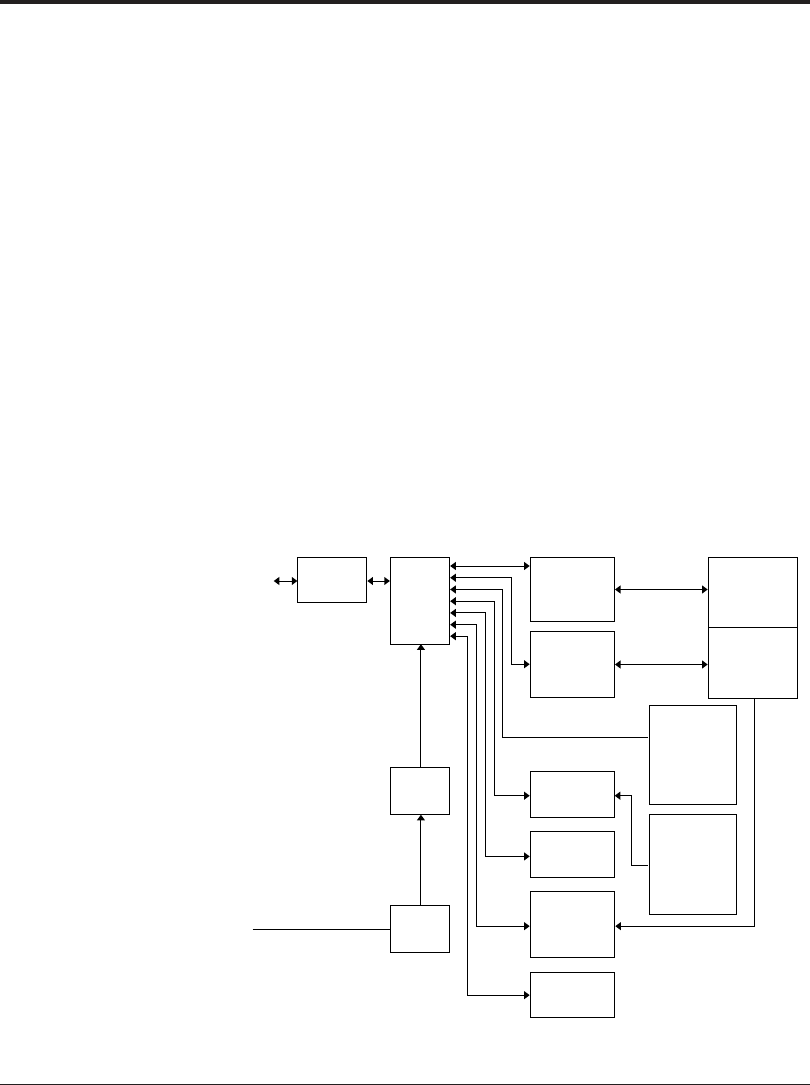
Figure 1.5 shows control block diagram.
Figure 1.5 Control block diagram
Host
machine
Interface
circuit
Control
circuit
(MPU )
Video
circuit
(front-side)
Video
circuit
(back-side)
Image
processing
circuit II
(option)
(front-side)
Duplex
circuit
Memory
board
Motor
driver
circuit
Operator
panel
Mechanism
unit
ADF
MF
Image
processing
circuit II
(option)
(back-side)
Power
supply
Power
switch
100 to 120 VAC
220 to 240 VAC