M3099EX/EH OEM Manual 3-5
INTERFACE
SPECIFICATIONS
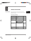
This section describes the video interface, which transfers the
scanning data from the scanner to the host computer.
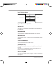
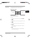
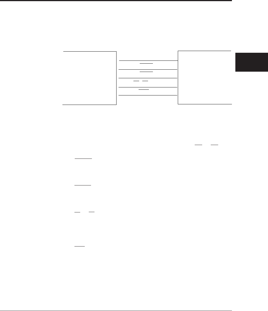
Video interface signals
Video Interface
➤
➤
➤
➤
➤
Host computer Scanner
VCL
HGATE
VGATE
V0 ~ V7 (8 lines)
FAIL
Figure 3.2 Video interface signal lines
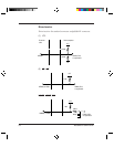
(1) VCL
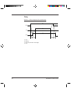
This signal is a sampling clock for the video data V0 to V7.
(2) HGATE
This signal indicates that the main scanning video data is valid.
(3) VGATE
This signal indicates that the subscanning video data is valid.
(4) V0 to V7
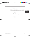
These signal lines carry the scanning video data. Logical “0”
indicates a black dot.
(5) FAIL
This signal indicates that a device error (MPU ROM/RAM
error) has occured in the scanner.


