


RX600 S4 Operating manual 105
CSS components Replacement of non-hot-plug components
8.2 Replacement of non-hot-plug components
8.2.1 Replacing a memory module
V CAUTION!
The actions described in this section may only be performed by
personnel with the appropriate technical training. Any unauthorized
openings and improper repairs could expose the user to risks
(electric shock, fire hazards) and could also damage the equipment.
Please observe the safety information in chapter “Important infor-
mation” on page 23.
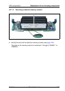
The system board has space for four memory boards (A, B, C and D), each of
which can be equipped with up to eight memory modules. The slots for the main
memory are suitable for 1 GB, 2 GB, 4 GB and 8 GB DDR2 / 533 or 667 MHz
FBDIMM memory modules. This allows a maximum memory configuration of
256 GB.
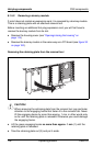
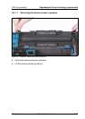
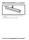
The memory boards are only accessible when the server is open.
V CAUTION!
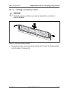
Each slot on a memory board must be filled either with a memory module
or a dummy module.
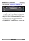
A possible memory module fault is reported by the CSS indicator lighting up on
the front and rear of the server or displayed on the ServerView Local Service
Display (for more information about the behavior of these indicators, see
chapter “Starting up and operation” on page 55 and the "Customer Self Service
(CSS)" manual on the ServerBooks DVD).
A memory module failure is reported by the CSS indicator flashing on the front
and rear of the server or displayed on the ServerView Local Service Display (for
more information about the behavior of these indicators, see chapter “Starting
up and operation” on page 55 and the "Customer Self Service (CSS)" manual
on the ServerBooks DVD).
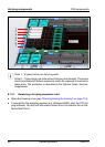
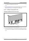
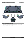
The faulty memory module can be identified from the corresponding LED when
the server is open (see figure 36 on page 106).