


28
H4D
20
2221
1716
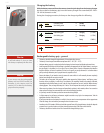
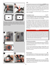
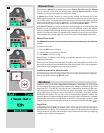
Two types of viewnder screens showing the dierence in
masking and composition frame marking. Type varies accord-
ing to sensor size. See Accessories for other types (with grid
pattern, for example).
Note
Do not attempt to clean the screen by immersing it in water, or use
any kind of cleaning uid. If the screen becomes damp, do not use
hot air to dry it. Use a soft cloth on the upper surface only. Seek
advice from an Authorized Hasselblad Service Center if the screen
becomes particularly soiled. Remember that particles or greasy
marks on the screen might impair the viewnder image but have
no eect whatsoever on the recorded image
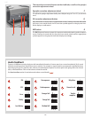
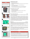
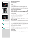
OFF
From the active screen, press (not click !) the red ON.OFF button
for a half second. All buttons (except the ON.OFF button) remain
ineective, producing virtually no demand on the battery. This
is the normal mode when transporting or storing the camera
or where there might be a risk of inadvertently activating the
camera. (However, remove the batteries if you are going to store
the camera for a period of more than a few weeks).
In this mode neither the viewnder display nor grip display infor-
mation is available.
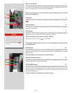
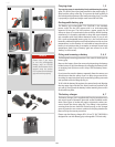
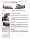
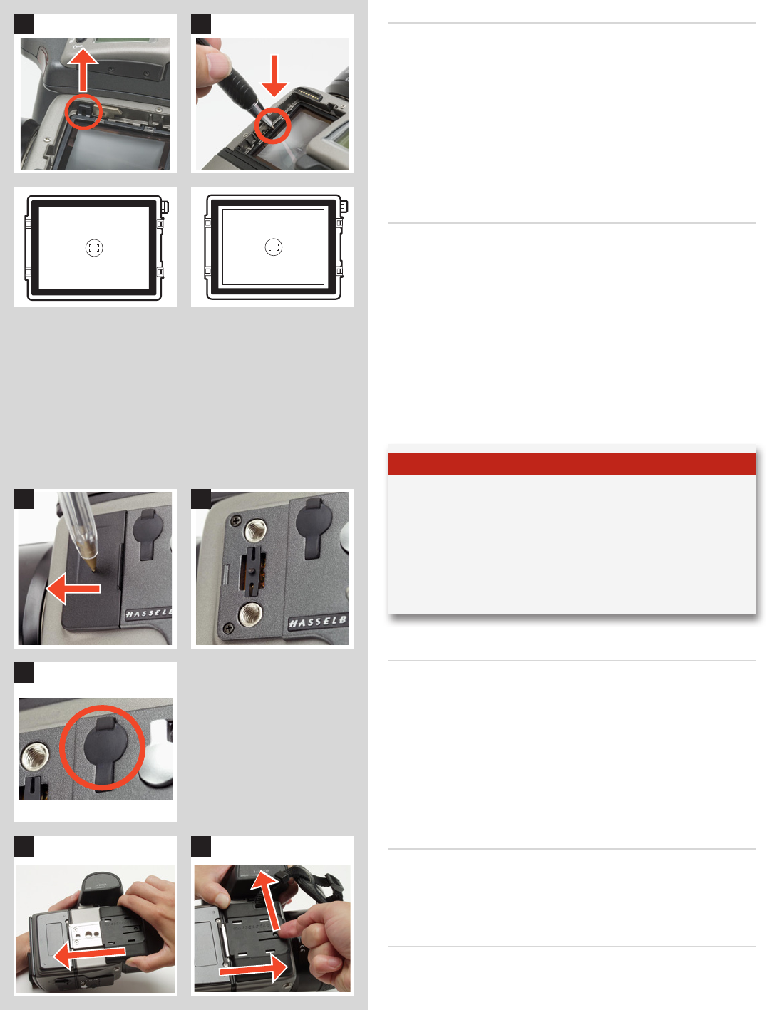
Viewnderscreen 16,17
The H4D is tted with a Spherical Acute-Matte D viewnder screen
for extreme brightness, clarity and even illumination. An optional
accessory screen with a grid pattern is also available.
To change a viewnder screen, remove the viewnder to access
the viewnder screen. To remove the screen, place the tip of a
ballpoint pen or similar in the viewnder screen removal lug and
pull upwards. To replace the screen, position the right side of the
screen in place so that it sits correctly in the recess. Place the tip
of a ballpoint pen or similar in the viewnder screen replacement
indentation and press downwards until the screen snaps into
position. Try to avoid touching either surface of the screen with
bare ngers.
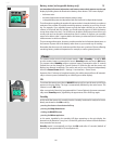
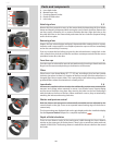
Accessoryconnection 18,19
On the left hand side of the camera body are two accessory-
retaining screw threads (M5), as well as a databus connector,
protected beneath a cover.
The cover can be removed by inserting a pointed object, such
as a pen, in the small hole and then sliding it to the left, as in the
illustration. The cover-retaining clip can then also be removed to
access the connector.
PC-connector 20
A PC connector for non TTL-ash synchronisation is located on
the left side of the body. It is protected by a captive rubber plug.
Protective base plate 21, 22
To attach the protective base plate, slip it over the camera foot
until it stops. To remove it, lift the securing catch while pushing
the plate back towards the lens.
18 19