


18
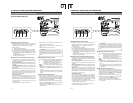
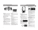
2. CONTROLS, INDICATORS AND CONNECTORS
STILLSTOPREW
BLANK SEARCH
FF PLAY
we q
r
!0 o
y t u
i
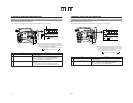
1 Cassette cover
The cassette cover can be opened by sliding the OPEN
knob2. Open this cover to insert or remove a videocassette
from the unit. Normally, this cover should be closed.
CAUTION:
To prevent foreign objects from entering the internal
parts of the VTR unit, do not leave the unit with the
cover open for extended periods of time.
2 [OPEN] Cassette cover lock knob
Slide this knob to open the cassette cover.
3 [EJECT] button
Located inside the cassette cover.
Press this button to eject the videocassette.
MEMO:
● It takes a few seconds before the videocassette is
ejected. Do not close the cassette cover during the
eject operation.
● Do not touch the cassette insertion slot or cassette
during the eject operation. This could result in
damage.
● Eject operation is not possible while the power is off.
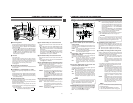
4 Operation cover
Open this cover when operating in the playback mode.
Otherwise, keep this cover closed.
This cover can be opened by sliding it to the side.
MEMO:
When the STOP button (6) is pressed in the Camera
mode to set the VTR operation mode indicator to
indicate STOP, playback operations become possible.
5 [PLAY] button
Press to start playback. During still picture playback and
search mode, press this button to return to the normal
playback mode.
* If the auto tracking is active at the moment the play mode
is entered, the playback video will be interfered with digital
noise.
6 [STOP] button
Press to enter the stop mode.
7 [STILL] button
Press to enter the still picture mode during playback, in the
stop mode or in the search mode.
When the still picture mode has continued for about 3
minutes, the unit automatically switches to the stop mode.
(Tape protect mode)
8 [FF] Fast forward button
Press this button to fast forward the tape.
● Pressing this button in the stop or rewind mode initiates
the fast forward mode.
● Pressing this button during playback, still picture playback
or reverse search initiates forward search.
9 [REW] Rewind button
Press this button to rewind the tape.
● Pressing this button in the stop or fast forward mode
initiates the rewind mode.
● Pressing this button during playback, still picture playback
or forward search initiates reverse search.
0 [BLANK SEARCH] button
Press this button to locate blank parts (unrecorded parts)
on the tape, such as the end point of a recording.
Blank search starts when this button is pressed in the stop
mode. When a blank part (unrecorded part) on the tape is
detected, the unit enters the STILL status in the VTR mode
and the Standby status in the Camera mode.
2-4 Top Section
19
2. CONTROLS, INDICATORS AND CONNECTORS
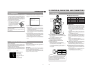
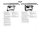
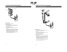
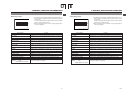
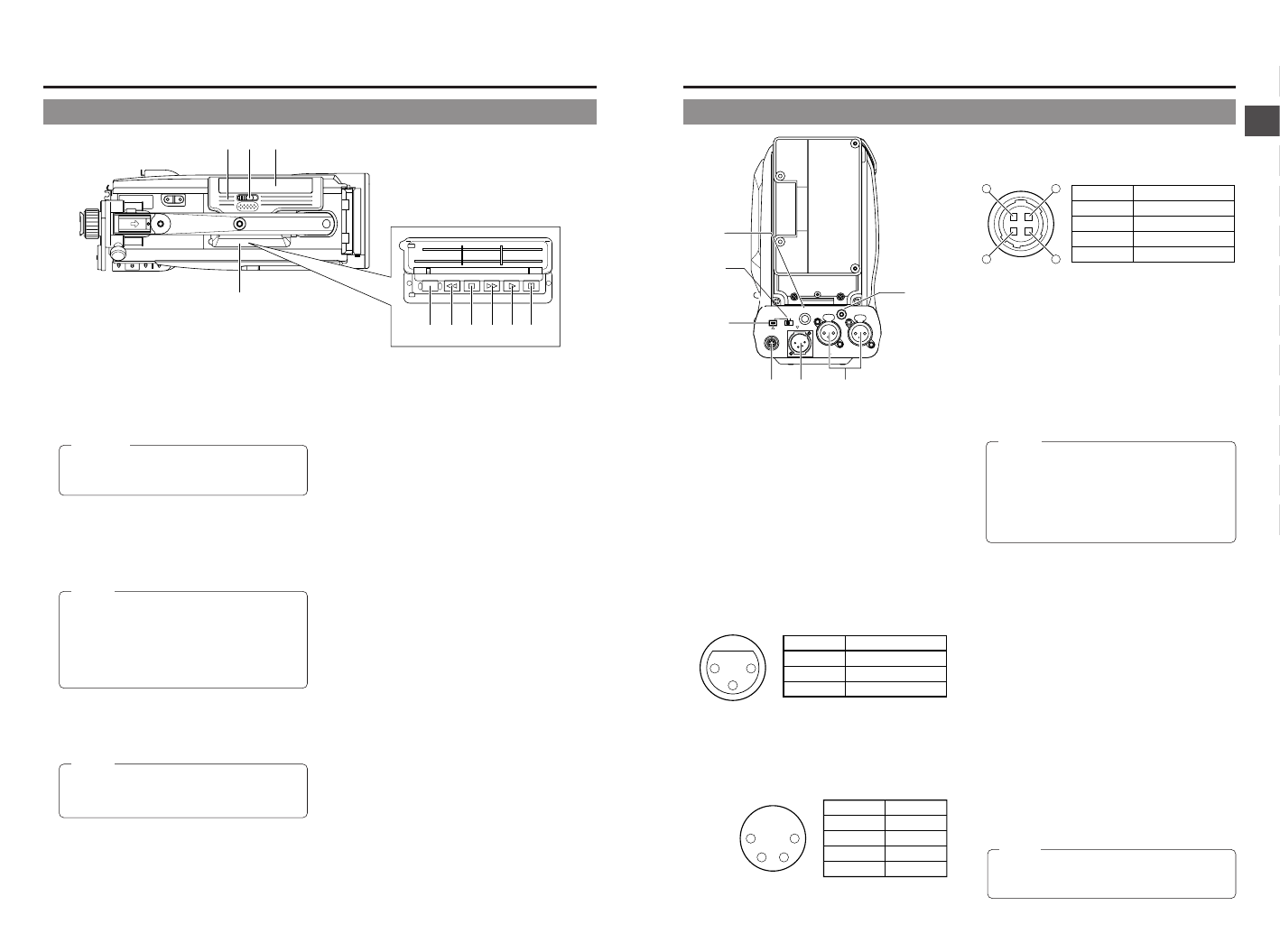
2-5 Rear Section
1 [TALLY] Tally lamp
This lamp lights up when the GY-DV5100 enters the record
mode. It blinks during the transition to the record mode.
● Use the BACK TALLY item on the OTHERS (2/2) menu
screen to select whether or not the lamp should light and
the lighting pattern.
☞ See “BACK TALLY” on page 87.
2 [CH-1/CH-2 REAR AUDIO IN] CH-1/CH-2 Audio
input connector on the rear section
Connect external audio equipment or a microphone to this
connector.
● Set the CH-1/CH-2 REAR AUDIO IN switch B on page
16 in accordance with the connected equipment.
● To record the audio signal input through this connector,
set the CH-1 or CH-2 AUDIO IN switch 0 on page 16 to
“REAR”. The audio from this connector is recorded on
the channel set to “REAR”.
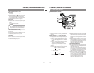
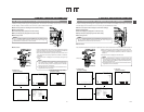
3 [DC IN] DC input connector (XLR 4-pin)
Power input connector for 12 V DC. Connect to the optional
AA-P250 power adapter. When a cable is connected here,
the power supply from the battery pack is interrupted and
the source is switched to the power supplied through this
connector.
1 4
32
No. Signal
GND
—
—
+12V
1
2
3
4
(Surface profile)
14
23
No. Signal
GND
—
—
DC 12V (power through)
1
2
3
4
No. Signal
GND
HOT
COLD
1
2
3
2
1
3
PHONES
DC OUT
DC IN
DV
INT
REAR AUDIO IN
TALLY
CH-1
CH-2
t
re w
y
q
u
4 [DC OUT] DC output connector
Connector for power output to a wireless microphone
transmitter, etc. The supply voltage is identical to the voltage
supplied to the unit (DC 17 V max. 0.3 A).
5 [PHONES] Earphone jack
This is a stereo mini-jack for connecting an earphone for
audio monitoring. Plug in an earphone or headphone with
a 3.5 mm diameter plug. The earphone can also be used to
monitor alarm tones in accordance with the circumstances.
The sound from the monitoring speaker is interrupted when
an earphone is connected here.
The audio channel to be output is selected with the AUDIO
SELECT item on the AUDIO/VIDEO menu screen and
MONITOR SELECT switch C on page 16.
The audio output level is adjusted with the Audio monitor
volume control 1 on page 12.
MEMO:
● The volume of the alarm sound is set with the ALARM
VR LEVEL item on the OTHERS (2/2) menu screen.
● When using a stereotype jack and stereo sound
should be output, the following setting should be
performed.
Set the MONITOR SELECT switch to “MIX”.
Set the AUDIO MONITOR item on the AUDIO/VIDEO
menu screen to STEREO.
6 [DV/INT]DV/INT selector switch
This switch is used to select whether to connect the optional
DV Disk Recorder to this camera or a digital video
component to the 7 DV connector.
DV: Connect a digital video component to the DV
connector
INT: Connect a DV Disk Recorder to the camera
* Turn the camera off before using this switch.
7 [DV] connector
Using a DV cable (optional), a digital video component with
DV connector can be connected here.
This connector is used for input and output of the DV signal
or to input the VTR control signal from a digital video
component with DV connector.
To record the DV signal from this connector, set the unit to
the VTR mode. (Press the MODE switch F on page 14
upward to turn on the VTR indicator.)
● Camera mode:
The DV compressed signal (IEEE1394) of the camera
image is output.
● VTR mode:
The DV input signal from this connector can be recorded
on tape. During playback, the tape playback DV
compressed signal is output.
MEMO:
To receive FF/REW remote control signals from this
connector, select the setting with the REM FF/REW
MODE item on the OTHERS (1/2) menu screen.