


51
6. SETTING AND ADJUSTMENTS BEFORE SHOOTING
MONITOR
EDITSEARCH
FILTER
STATUS
SHUTTER
MENU
AUTO IRIS
BACK L
NORMAL
SPOT L
STRETCH
NORMAL
COMPRESS
FULL AUTO BLACK LOLUX
MODE
POWER
ON OFF
VTR
OPEN
VTR
CAM
1
3200K
5600K
5600K
5600K
ND
/
/
ND
2
.3
.4
1
8
1
64
CH-1
AUDIO IN
AUDIO SELECT
CH-2
CH-1 CH-2
FRONT
REAR
AUTO
MANUAL
AUDIO
LEVEL
CH-1 CH-2
PULL
OPEN
LCDBRIGHT DISPLAY
COUNTER
CH-1
AUDIO IN
AUDIO SELECT
CH-2
CH-1 CH-2
FRONT
REAR
AUTO
MANUAL
TC GENE.
TC
MONITOR
SELECT
AUDIO
LEVEL
REAR
AUDIO IN
CH-1 CH-2
CH-1
MIX
CH-2
CH-1 CH-2
LINE
MIC
+48V
PRST
REGEN FREE
REC
UB
LCDBRIGHT DISPLAY
VF
ZEBRA
AUDIO
LEVELE CH-1
OFF
ON
SKIN
AREA
AUTO
WHITE
ACCU
FOCUS
VTR
5
FRONT MIC +48V
OFF
ON
PHONES
DC OUT
DC IN
DV
INT
REAR AUDIO IN
TALLY
CH-1
CH-2
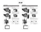
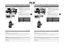
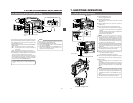
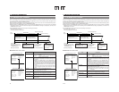
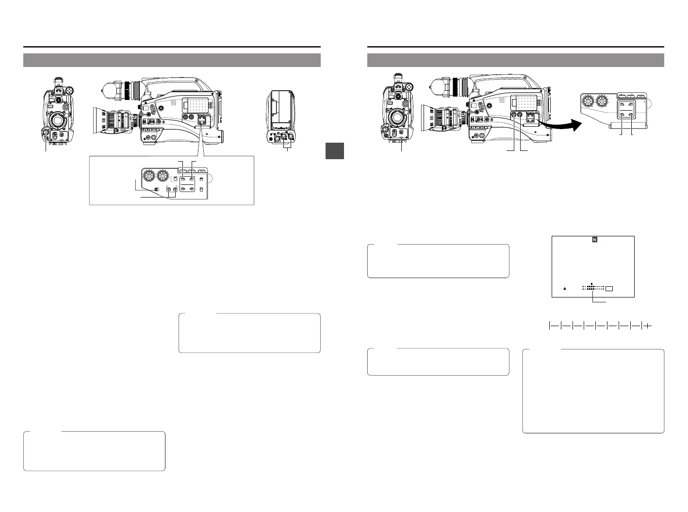
6-7 Audio Input Signal Selection
REAR AUDIO IN
connector
FRONT MIC IN
connector
REAR AUDIO IN
(LINE/MIC) switch
CH-1 AUDIO IN switch CH-2 AUDIO IN
switch
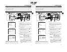
■Selecting the REAR AUDIO IN connector
Select the sound to be input to the REAR AUDIO IN connector
using the REAR AUDIO IN (LINE/MIC) switch. The setting is
made individually for both the REAR AUDIO IN connector.
LINE : Set to this position when connected to audio
equipment, etc.
The reference input level is +4 dBs.
MIC : Set to this position when using a monaural
microphone.
The reference input level is –60 dBs.
+48 V : Set to this position when a microphone
(phantom microphone) requiring +48 V DC
power supply is connected.
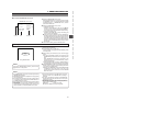
CAUTION:
Before connecting a component that does not require +48
V power supply, make sure that the REAR AUDIO IN (LINE/
MIC) switch is not set to +48 V.
Neglecting this could cause damage to the connected
component.
FRONT MIC +48V
(ON/OFF) switch
The GY-DV5100 is provided with the FRONT MIC IN connector
and the REAR AUDIO IN connector for audio input.
Two channels of sound can be recorded on the tape in digital
PCM format. Using the AUDIO IN switch, select for each
channel (CH-1 and CH-2) whether the sound to be recorded
should be the sound from the FRONT MIC IN connector or the
sound from the REAR AUDIO IN connector.
■Selecting the CH-1 channel input sound
Make the selection using the CH-1 AUDIO IN switch.
FRONT: The sound from the FRONT MIC IN connector is
recorded on the CH-1 channel.
REAR : The sound from the REAR AUDIO IN connector is
recorded on the CH-1 channel.
■Selecting the CH-2 channel input sound
Make the selection using the CH-2 AUDIO IN switch.
FRONT: The sound from the FRONT MIC IN connector is
recorded on the CH-2 channel.
REAR : The sound from the REAR AUDIO IN connector is
recorded on the CH-2 channel.
■Selecting the FRONT MIC IN connector
Select the microphone to connect to the FRONT MIC IN
connector using the FRONT MIC +48V (ON/OFF) switch.
ON: Set to this position when a microphone requiring
+48 V power supply (phantom microphone) is
connected.
Use this setting to connect the included
microphone to the FRONT MIC IN connector.
OFF: Set to this position when connecting a
microphone that does not require +48 V power
supply.
CAUTION:
Before connecting a component that does not require +48 V
power supply, make sure that the FRONT MIC +48V (ON/
OFF) switch is not set to ON.
Neglecting this could cause damage to the connected
component..
52
6. SETTING AND ADJUSTMENTS BEFORE SHOOTING
00:00:00:00
20
min
FAS
–3dB
FAW
I
SD
FIL1
B
F5
.6
48
k
12
.2V
ED.FWD 01/02/03
AM
01:23:45
∞ –26 –20 –15 –11 –7 –3 0dB OVER
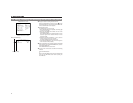
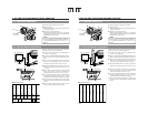
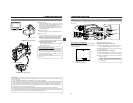
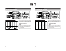
6-8 Recording Level Adjustment
Indicator level (reference)
MONITOR
EDITSEARCH
FILTER
STATUS
SHUTTER
MENU
AUTO IRIS
BACK L
NORMAL
SPOT L
STRETCH
NORMAL
COMPRESS
FULL AUTO BLACK LOLUX
MODE
POWER
ON OFF
VTR
OPEN
VTR
CAM
1
3200K
5600K
5600K
5600K
ND
/
/
ND
2
.3
.4
1
8
1
64
CH-1
AUDIO IN
AUDIO SELECT
CH-2
CH-1 CH-2
FRONT
REAR
AUTO
MANUAL
AUDIO
LEVEL
CH-1 CH-2
PULL
OPEN
LCDBRIGHT DISPLAY
VF
ZEBRA
AUDIO
LEVELE CH-1
OFF
ON
SKIN
AREA
AUTO
WHITE
ACCU
FOCUS
VTR
5
CH-1
AUDIO IN
AUDIO SELECT
CH-2
CH-1 CH-2
FRONT
REAR
AUTO
MANUAL
AUDIO
LEVEL
CH-1 CH-2
PULL
OPEN
LCDBRIGHT DISPLAY
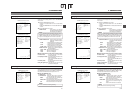
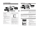
CH-2 AUDIO
SELECT switch
CH-1 audio input level control
CH-1 audio input level control CH-2 audio input level control
CH-1 AUDIO SELECT switch
Viewfinder Status 1 Mode
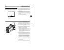
■Using the audio input level control on the front section
1
Set the audio input level control on the front section to
maximum (10) position.
2
Initially, adjust the audio input level using the CH-1 audio
input level control on the side.
3
If a loud sound is input during recording, use the audio
input level control on the front section to lower the audio
input level.
For each audio channel, use the AUDIO SELECT switches to
select whether the audio level adjustment should be set to AUTO
mode or MANUAL mode.
● When set to AUTO : Audio input level is fixed. In this
mode, the audio input level
control does not function.
● When set to MANUAL: Audio input level can be adjusted
using the audio input level
controls for each audio input.
(The AUTO mode is selected in
the Full Auto shooting mode.)
MEMO:
The reference level for audio recorded on the tape can be
set with the AUDIO REF. LEVEL item on the AUDIO/VIDEO
menu screen. (–20 dB or –12 dB). The level will change for
both CH-1 and CH-2.
■Adjusting the audio input level control on the front
section
The audio input level control on the front section only affects
the CH-1 channel sound.
To use the audio input level control on the front section, make
the following settings.
● Set the CH-1 AUDIO SELECT switch to MANUAL.
● Set the CH1 FRONT VR. item on the AUDIO/VIDEO menu
screen to ENABLE.
MEMO:
The audio input level controls on the side section work
regardless of the setting of CH1 FRONT VR. item on the
AUDIO/VIDEO menu screen.
The audio input level can be adjusted manually when the GY-
DV5100 is in the record, record-standby or stop mode.
1.
Set the AUDIO SELECT switch of the channel whose audio
level that you want to adjust manually to MANUAL.
2.
Rotate the audio input level control corresponding to the
audio input level to be adjusted.
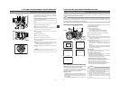
● Adjust so that the peak level does not exceed the –3dB
point when a loud sound is input.
CAUTION:
● When the REAR AUDIO IN LINE/MIC switch is set to
MIC, be sure to check that the microphone is connected
to the REAR AUDIO IN connector. If the microphone is
not connected, increasing the audio level could cause
noise from the input connector to be recorded on the
tape. When the microphone is not connected to the
REAR AUDIO IN connector, set the REAR AUDIO IN
LINE/MIC switch to LINE or turn down the audio level
control.
● In the Full Auto shooting mode, the audio level volume
cannot be adjusted with the audio level controls on the
front and side sections.
Audio level