


66
9. USING EXTERNAL COMPONENTS
MONITOR
EDITSEARCH
FILTER
STATUS
SHUTTER
MENU
AUTO IRIS
BACK L
NORMAL
SPOT L
STRETCH
NORMAL
COMPRESS
FULL AUTO BLACK LOLUX
MODE
POWER
ON OFF
VTR
OPEN
VTR
CAM
1
3200K
5600K
5600K
5600K
ND
/
/
ND
2
.3
.4
1
8
1
64
CH-1
AUDIO IN
AUDIO SELECT
CH-2
CH-1 CH-2
FRONT
REAR
AUTO
MANUAL
AUDIO
LEVEL
CH-1 CH-2
PULL
OPEN
LCDBRIGHT DISPLAY
MODE
VTR
CAM
DV
INT
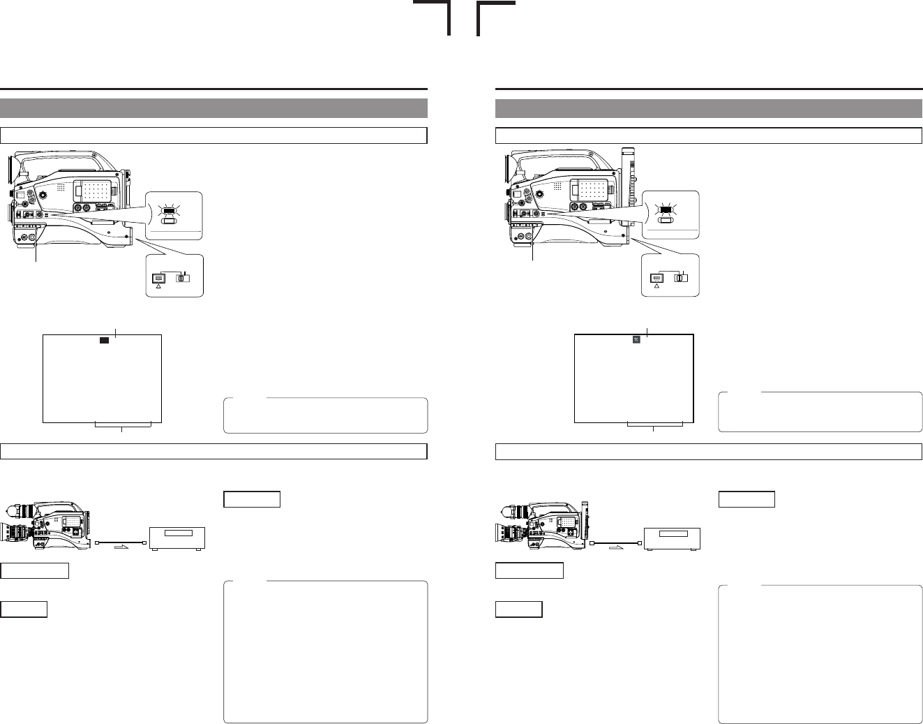
TC00:00:00:00
REC 01/02/03 01:23:45
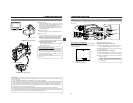
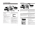
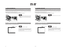
MODE switch
Date and time data:
Data transmitted from the playback unit
is recorded.
Time code:
The data generated by the GY-DV5100’s time code generator
is recorded.
Date and time
Master unit
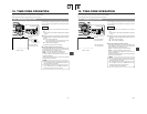
Backup Recording of the GY-DV5100's Camera Image and Sound Through the DV Connector
1.
Switch the DV/INT selector switch on the rear of the camera
to DV.
2.
Turn ON both units.
3.
Place the GY-DV5100 in the VTR MODE.
Press the MODE switch upward to turn on the VTR indicator.
4.
Insert the videocassettes.
GY-DV5100: Insert the videocassette to be dubbed to.
Playback unit: Insert the recorded videocassette.
5.
Connect the units with the DV cable.
6.
Start playback on the playback unit.
For details, see the instructions to the unit used for playback.
● The playback picture from the playback unit appears on
the GY-DV5100’s LCD monitor and viewfinder screen.
7.
Press the VTR trigger on the GY-DV5100 to start recording.
■To temporarily pause the recording, press the VTR trigger.
■To restart the recording, press the VTR trigger again.
8.
When dubbing is completed.
Press the VTR trigger or the STOP button on the
GY-DV5100 to stop recording, and then stop playback on
the playback unit.
Time code
MONITOR
EDITSEARCH
FILTER
STATUS
SHUTTER
MENU
AUTO IRIS
BACK L
NORMAL
SPOT L
STRETCH
NORMAL
COMPRESS
FULL AUTO BLACK LOLUX
MODE
POWER
ON OFF
VTR
OPEN
VTR
CAM
1
3200K
5600K
5600K
5600K
ND
/
/
ND
2
.3
.4
1
8
1
64
CH-1
AUDIO IN
AUDIO SELECT
CH-2
CH-1CH-2
FRONT
REAR
AUTO
MANUAL
AUDIO
LEVEL
CH-1 CH-2
PULL
OPEN
LCD BRIGHT DISPLAY
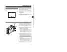
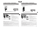
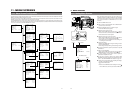
The GY-DV5100’s camera image and sound can be recorded for backup on another component that is equipped with DV connector.
Recording operation is performed on the backup equipment simultaneously with performance of the recording operations on the
GY-DV5100.
Connections
Use the GY-DV5100 as the master unit.
Connect the master unit and the backup unit with a DV cable
DV cable
Signal flow
Backup unit
Settings
■Master unit (GY-DV5100)
● Place in CAMERA mode.
● Set the DV REC TRIGGER item on the OTHERS (1/2)
Menu Screen to ON.
■Backup unit
● Place in DV signal input mode.
* Depending on the used component, it may be necessary
to set “REMOTE SELECT”.
● When BR-DV600A or BR-DV3000 is used, set the Backup
Recording function to OFF.
● Insert the tape and set to STOP or REC PAUSE status.
Operation
Start and stop of recording on the backup unit takes place in
accordance with the operation of the VTR trigger button on the
master unit.
Start and stop of recording on the backup unit takes place in
accordance with start and stop of recording on the master unit.
(Depending on the GY-DV5100 or the backup unit, the image,
audio, and/or time code may deviate from what they should be
at the points where the recording is started or stopped.)
MEMO:
● When the backup recording is started, the “TRIGGER
TO DV” indication is shown on the LCD or in the
viewfinder for 3 seconds.
● When the Backup Recording function of BR-DV600A or
BR-DV3000 is used, the DV REC TRIGGER item on the
GY-DV5100’s OTHERS (1/2) Menu Screen should be
set to OFF.
● If the backup device is equipped with a feature to record
time codes input from the DV IN/OUT terminal (TC
DUPLICATE feature), time code data the same as on
the master side can be recorded.
● When using BR-DV600A as a backup device and
switching GY-DV5100 from the EDIT SEARCH or
PLAYBACK mode to the RECORD mode, noise will be
noticed on the monitor output screen of BR-DV600A
(backup will be correctly recorded).
MEMO:
Depending on the player, sound may not be heard
momentarily from this unit when switching modes from
STILL to PLAY.
9-1 Connecting a Video Component with DV Connector (Cont’d)
When Using the GY-DV5100 as RECORDING Unit (Dubbing From Another Videocassette)
9. USING EXTERNAL COMPONENTS
E-66
MONITOR
EDITSEARCH
FILTER
STATUS
SHUTTER
MENU
AUTO IRIS
BACK L
NORMAL
SPOT L
STRETCH
NORMAL
COMPRESS
FULL AUTO BLACK LOLUX
MODE
POWER
ON OFF
VTR
OPEN
VTR
CAM
1
3200K
5600K
5600K
5600K
ND
/
/
ND
2
.3
.4
1
8
1
64
CH-1
AUDIO INPUT
AUDIO SELECT
CH-2
CH-1 CH-2
FRONT
REAR
AUTO
MANUAL
AUDIO
LEVEL
CH-1 CH-2
PULL
OPEN
LCDBRIGHT DISPLAY
MODE
VTR
CAM
DV
INT
00:00:00:00
REC 01/02/03 01:23:45
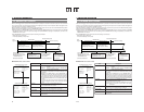
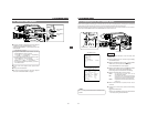
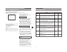
MODE switch
Date and time data:
Data transmitted from the playback
unit is recorded.
Time code:
The data generated by the GY-
DV5101’s time code generator is
recorded.
Date and time
Master unit
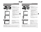
When Using the GY-DV5101 as RECORDING Unit (Dubbing From Another Videocassette)
Backup Recording of the GY-DV5100’s Camera Image and Sound Through the DV Connector
1.
Switch the DV/INT selector switch on the rear of the camera
to DV.
2.
Tu rn ON both units.
3.
Place the GY-DV5101 in the VTR MODE.
Press the MODE switch upward to turn on the VTR indicator.
4.
Insert the videocassettes.
GY-DV5101: Insert the videocassette to be dubbed to.
Playback unit: Insert the recorded videocassette.
5.
Connect the units with the DV cable.
6.
Start playback on the playback unit.
For details, see the instructions to the unit used for playback.
● The playback picture from the playback unit appears on
the GY-DV5101’s LCD monitor and viewfinder screen.
7.
Press the VTR trigger on the GY-DV5101 to start recording.
■To temporarily pause the recording, press the VTR trigger.
■To restart the recording, press the VTR trigger again.
8.
When dubbing is completed.
Press the VTR trigger or the STOP button on the
GY-DV5101 to stop recording, and then stop playback on
the playback unit.
Time code
MONITOR
EDITSEARCH
FILTER
STATUS
SHUTTER
MENU
AUTO IRIS
BACK L
NORMAL
SPOT L
STRETCH
NORMAL
COMPRESS
FULL AUTO BLACK LOLUX
MODE
POWER
ON OFF
VTR
OPEN
VTR
CAM
1
3200K
5600K
5600K
5600K
ND
/
/
ND
2
.3
.4
1
8
1
64
CH-1
AUDIO IN
AUDIO SELECT
CH-2
CH-1CH-2
FRONT
REAR
AUTO
MANUAL
AUDIO
LEVEL
CH-1 CH-2
PULL
OPEN
LCD BRIGHT DISPLAY
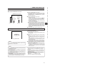
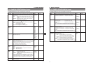
The GY-DV5100’s camera image and sound can be recorded for backup on another component that is equipped with DV connector.
Recording operation is performed on the backup equipment simultaneously with performance of the recording operations on the
GY-DV5100.
Connections
Use the GY-DV5100 as the master unit.
Connect the master unit and the backup unit with a DV cable
DV cable
Signal flow
Backup unit
Settings
■Master unit (GY-DV5100)
● Place in CAMERA mode.
● Set the DV REC TRIGGER item on the OTHERS (1/2)
Menu Screen to ON.
■Backup unit
● Place in DV signal input mode.
* Depending on the used component, it may be necessary
to set “REMOTE SELECT”.
● When BR-DV600A or BR-DV3000 is used, set the Backup
Recording function to OFF.
● Insert the tape and set to STOP or REC PAUSE status.
Operation
Start and stop of recording on the backup unit takes place in
accordance with the operation of the VTR trigger button on the
master unit.
Start and stop of recording on the backup unit takes place in
accordance with start and stop of recording on the master unit.
(Depending on the GY-DV5100/5101 or the backup unit, the
image, audio, and/or time code may deviate from what they
should be at the points where the recording is started or
stopped.)
MEMO:
● When the backup recording is started, the “TRIGGER
TO DV” indication is shown on the LCD or in the
viewfinder for 3 seconds.
● When the Backup Recording function of BR-DV600A or
BR-DV3000 is used, the DV REC TRIGGER item on the
GY-DV5100’s OTHERS (1/2) Menu Screen should be
set to OFF.
● If the backup device is equipped with a feature to record
time codes input from the DV IN/OUT terminal (TC
DUPLICATE feature), time code data the same as on
the master side can be recorded.
● When using BR-DV600A as a backup device and
switching GY-DV5100 from the EDIT SEARCH or
PLAYBACK mode to the RECORD mode, noise will be
noticed on the monitor output screen of BR-DV600A
(backup will be correctly recorded).
MEMO:
Depending on the player, sound may not be heard
momentarily from this unit when switching modes from
STILL to PLAY.
9-1 Connecting a Video Component with DV Connector (Cont’d)
E
U