


37
4. POWER SUPPLY
5.
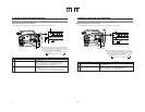
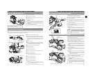
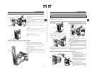
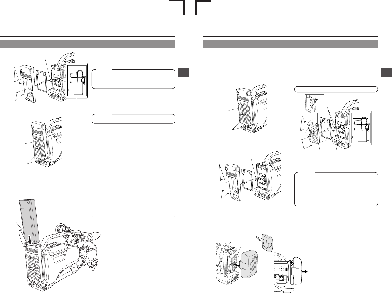
Connect the connector and battery holder connector coming
out of the camera.
6.
Attach the battery case with the four mount screws B.
5.
6.
6.
8.
Black screws A
7.
Connector
Mount screws B
Mount screws B
Following connection of the connectors, insert them into
the connector compartment.
Take care not to pinch the wires. This could result in
damage.
CAUTION:
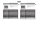
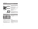
Using a Flat Shape Type Battery Pack (optional)
Be sure to set the POWER switch to OFF before replacing
the battery pack.
Attaching a Flat Shape Type Battery Pack
1.
Open the battery case cover while pushing the lock release
lever.
2.
Insert the battery pack into the battery case with its
electrodes facing the unit.
3.
Close the battery case cover.
Lock release
lever
7.
Attach the battery case cover.
8.
Attach the two battery case black screws A.
Mount screws B use M3 × 6 mm screws.
CAUTION:
Wire layout
4. POWER SUPPLY
E-37
4.
5.
5.
4.
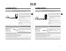
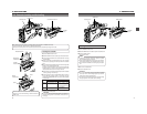
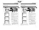
Connect the 2 connectors protruding from the battery holder
to the connectors on the camera.
5.
Secure the battery holder to the GY-DV5100 with the four
mount screws provided with the battery holder.
3.
3.
3.
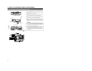
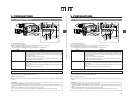
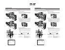
Using an Anton-Bauer Battery Pack
To use an Anton-Bauer battery pack (DIONIC 90, Propack 13/14, Trimpack 13/14, Magnum 13/14, Compack 13/14 Series), it is
necessary to detach the battery case from the GY-DV5100 and replace it with the Anton-Bauer battery holder. Use the following
battery holder.
• Battery holder: Anton-Bauer QR JVC DIGI
Detaching the Battery Case From the GY-DV5100 and Attaching The Anton-
Bauer Battery
1.
Remove the two black screws A on the battery case.
2.
Remove the lower half of the battery case cover in the
downward direction.
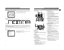
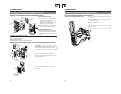
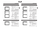
Attaching and Detaching an Anton-Bauer Battery Pack
Attaching the Battery Pack
1.
Align the 3 guide pins of the battery pack with
the guide holes on the battery holder, and push
straight to insert the battery pack.
The battery cannot be attached properly if the
guide pins are not inserted straight.
2.
Slide the battery pack toward the side panel
where the cassette cover is located until it clicks.
Now the battery pack has been attached.
Detaching the Battery Pack
■While pushing the release lever, slide the battery
pack toward the side panel where the LCD display
is located, then pull the battery pack outward to
remove.
3.
Toremove the battery case, remove the four screws Bfixing
the battery case and the connector connecting the battery
case to this unit.
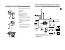
Attaching the Anton-Bauer Battery Holder
1.
Black screw A
2.
OPEN
CH-1
AUDIO INPUT
AUDIO SELECT
CH-2
CH-1 CH-2
FRONT
REAR
AUTO
MANUAL
AUDIO
LEVEL
CH-2
PULL
OPEN
LCDBRIGHT DISPLAY
Battery
Release lever
Anton-Bauer
Battery holder
Connector
Compartment
Guide pins
Battery pack
Release
lever
Cassette cover side panel
Guide holes
(×3)
Side panel
with display
Connector
Mount screw B
Mount screw B
● Following connection of the connectors, insert them into
the connector compartment.
Ta ke care not to pinch the wires. This could result in
damage.
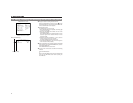
● The Anton-Bauer Battery Holder has pin connectors. Be
careful not to touch these pin terminals when attaching
or removing the battery and holder. Doing so may cause
injury.
CAUTION:
Wire layout
Be careful of pins.
E
U