


53
6. SETTING AND ADJUSTMENTS BEFORE SHOOTING
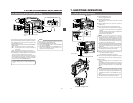
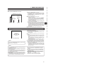
The audio input during recording, in record-pause or stop mode
can be monitored through the monitoring speaker or earphone.
● The monitoring audio is not output from the speaker while
the PHONES jack is in use.
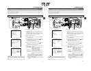
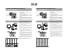
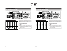
● Select the audio channel to be monitored using the MONITOR
SELECT switch.
CH-1 : The sound input to the CH-1 channel is output.
MIX : The sound input to the CH-1 and CH-2 channels is
output mixed.
CH-2 : The sound input to the CH-2 channel is output.
● The Monitoring volume control adjusts the monitoring volume.
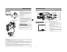
● The loudspeaker or earphone outputs an alarm tone in the
case of an abnormal condition occurring in the unit.
An alarm tone is also output when the tape end is reached or
when the battery is running down. The volume of the alarm
tone is set with the ALARM VR LEVEL item on the OTHERS
(2/2) menu screen. (OFF/LOW/MIDDLE/HIGH)
*Do not increase the audio monitoring volume excessively;
otherwise howling with the camera microphone may
occur.
6-9 Monitoring Audio during Recording
MEMO:
When connecting a stereotype earphone, make the
following settings to output stereo sound.
● Set the MONITOR SELECT switch to MIX.
● Set the AUDIO MONITOR item on the AUDIO/VIDEO
menu screen to STEREO.
● When AUDIO MONITOR in the AUDIO/VIDEO menu
screen is set to “STEREO”, only the audio of CH-1 is
output from the monitoring speaker.
MONITOR
EDITSEARCH
FILTER
STATUS
SHUTTER
MENU
AUTO IRIS
BACK L
NORMAL
SPOT L
STRETCH
NORMAL
COMPRESS
FULL AUTO BLACK LOLUX
MODE
POWER
ON OFF
VTR
OPEN
VTR
CAM
1
3200K
5600K
5600K
5600K
ND
/
/
ND
2
.3
.4
1
8
1
64
CH-1
AUDIO INPUT
AUDIO SELECT
CH-2
CH-1 CH-2
FRONT
REAR
AUTO
MANUAL
AUDIO
LEVEL
CH-1 CH-2
PULL
OPEN
LCDBRIGHT DISPLAY
COUNTER
CH-1
AUDIO IN
AUDIO SELECT
CH-2
CH-1 CH-2
FRONT
REAR
AUTO
MANUAL
TC GENE.
TC
MONITOR
SELECT
AUDIO
LEVEL
REAR
AUDIO IN
CH-1 CH-2
CH-1
MIX
CH-2
CH-1 CH-2
LINE
MIC
+48V
PRST
REGEN FREE
REC
UB
LCDBRIGHT DISPLAY
FRONT MIC +48V
OFF
ON
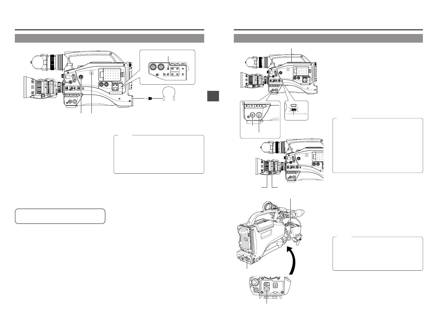
MONITOR SELECT switch
Monitoring volume
control
Monitoring speaker
PHONES jack
54
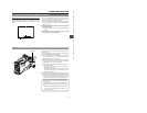
7. SHOOTING OPERATION
7-1 Basic Recording Operation
ZEBRA
AUDIO
LEVELE CH-1
OFF
ON
SKIN
AREA
AUTO
WHITE
ACCU
FOCUS
VTR
5
7. 8. 9.
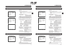
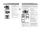
VTR trigger button
7. 8. 9.
VTR trigger button
8.
TALLY lamp
MONITOR
EDITSEARCH
FILTER
STATUS
SHUTTER
MENU
AUTO IRIS
BACK L
NORMAL
SPOT L
STRETCH
NORMAL
COMPRESS
FULL AUTO BLACK LOLUX
MODE
POWER
ON OFF
VTR
OPEN
VTR
CAM
1
3200K
5600K
5600K
5600K
ND
/
/
ND
2
.3
.4
1
8
1
64
CH-1
AUDIO IN
AUDIO SELECT
CH-2
CH-1 CH-2
FRONT
REAR
AUTO
MANUAL
AUDIO
LEVEL
CH-1 CH-2
PULL
OPEN
LCDBRIGHT DISPLAY
POWER
ON OFF
VTR
MODE
VTR
CAM
3.
2.
1.
7. 8. 9.
OPEN knob
MONITOR
EDITSEARCH
FILTER
STATUS
SHUTTER
MENU
AUTO IRIS
BACK L
NORMAL
SPOT L
STRETCH
NORMAL
COMPRESS
FULL AUTO BLACK LOLUX
MODE
POWER
ON OFF
VTR
VTR
CAM
1
3200K
5600K
5600K
5600K
ND
/
/
ND
2
.3
.4
1
8
1
64
C
H
A
C
H
AUDIO
LEVEL
CH-1 CH-2
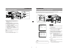
6.
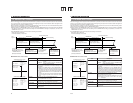
Focusing ring
6.
Zoom ring
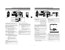
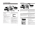
1.
Set the POWER switch to ON.
● Power is supplied to the unit.
2.
The CAM indicator lights up.
The GY-DV5100 is in the Camera mode when the CAM
indicator is on.
3.
Slide the OPEN switch on the top section to open the
cassette cover.
4.
Insert a videocassette into the cassette insertion slot.
● Ensure that the erasure-prevention switch on the back of
the cassette is set to REC and insert a videocassette
properly.
When the cassette is inserted, the tape is loaded and the
unit enters the record-standby mode.
● Slowly close the cassette cover.
MEMO:
● Use a standard DV videocassette or a MiniDV
videocassette. (When a DVCAM cassette is used for
recording, longer recording can be performed than the
time indicated on the DVCAM cassette. For the recording
time, regard the remaining tape indication displayed on
the LCD or in the viewfinder as a guide.)
● Following loading of the cassette and when the POWER
switch is turned ON/OFF, the built-in head cleaner will
emit a sound while operating. This does not indicate a
malfunction.
● After the cassette cover is closed, it takes about 10
seconds before the unit is ready for recording.
5.
Adjust the camera section settings and the white balance.
☞ See “Camera Settings” on page 47.
☞ See “White Balance Adjustment” on page 50.
6.
Point the camera at the subject and determine the angle of
view and focus with the zoom lever and the focusing ring.
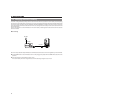
7.
Start recording.
Press the VTR trigger button on the GY-DV5100 to start
recording.
Once recording has started, the BACK TALLY lamp on the
rear section of the unit and the tally lamp on the viewfinder
light red, and the REC indication in the viewfinder lights
green.
MEMO:
● The lightening conditions of the BACK TALLY lamp on
the rear section of the unit and the tally lamp on the
viewfinder can be changed by setting the BACK TALLY
and FRONT TALLY items on the OTHERS (2/2) menu
screen.
● Menu operations cannot be performed when an optional
DV Disk Recorder is connected and is recording.