


65
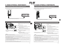
9. USING EXTERNAL COMPONENTS
MONITOR
EDITSEARCH
FILTER
STATUS
SHUTTER
MENU
AUTO IRIS
BACK L
NORMAL
SPOT L
STRETCH
NORMAL
COMPRESS
FULL AUTO BLACK LOLUX
MODE
POWER
ON OFF
VTR
OPEN
VTR
CAM
1
3200K
5600K
5600K
5600K
ND
/
/
ND
2
.3
.4
1
8
1
64
CH-1
AUDIO IN
AUDIO SELECT
CH-2
CH-1 CH-2
FRONT
REAR
AUTO
MANUAL
AUDIO
LEVEL
CH-1 CH-2
PULL
OPEN
LCDBRIGHT DISPLAY
MODE
VTR
CAM
DV
INT
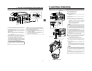
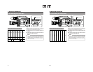
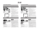
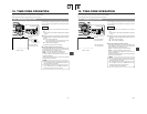
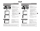
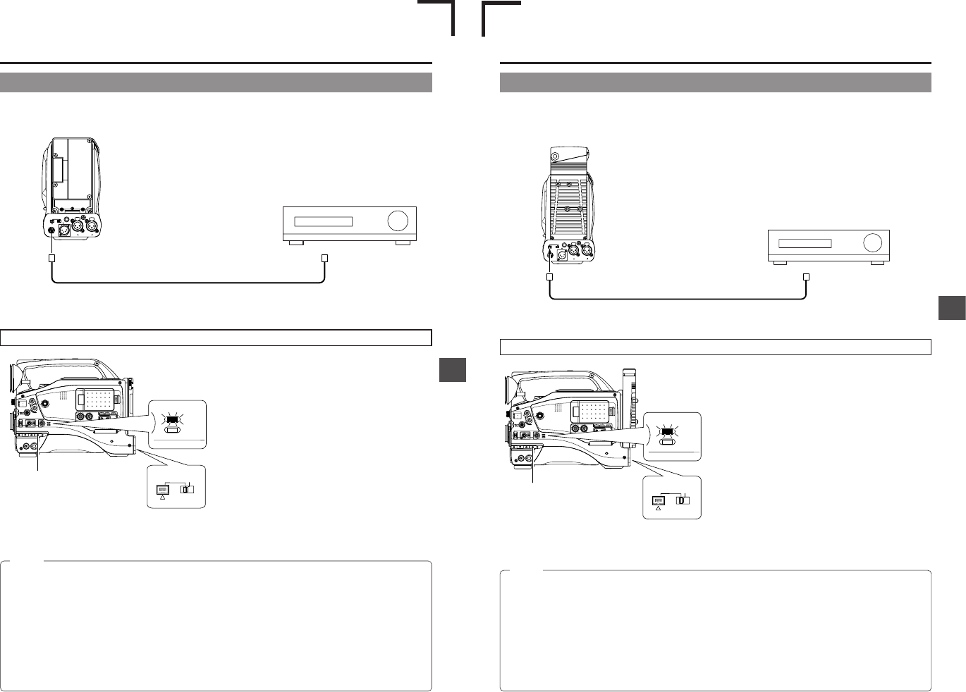
9-1 Connecting a Video Component with DV Connector
PHONES
DC OUT
DC IN
DV
INT
REAR AUDIO IN
TALLY
CH-1
CH-2
Connecting the GY-DV5100 to another video component equipped with DV I/O connector (IEEE1394 standard) using a DV cable
(optional) enables dubbing of digital signals with high picture quality and high-quality sound.
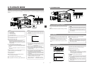
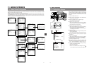
1.
Connect the units with the DV cable.
2.
Switch the DV/INT selector switch on the rear of the camera
to DV.
3.
Turn ON both units.
4.
Place the GY-DV5100 in the VTR MODE.
Press the MODE switch upward to turn on the VTR indicator.
5.
Insert the videocassettes.
GY-DV5100: Insert the recorded videocassette.
Recording unit: Insert the videocassette to be dubbed to.
6.
Press the PLAY button on the GY-DV5100 to start playback.
7.
Start recording on the recording unit.
For details, see the instructions to the unit used for
recording.
8.
When dubbing is completed.
Stop recording on the recording unit, and then press the
STOP button on the GY-DV5100 to stop playback.
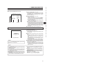
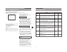
MEMO:
● Turn the camera off before switching DV/INT.
● The operation methods differ with the characteristics and specifications of the connected equipment. Even if connection is
possible, operation or data communication may sometimes be impossible to perform.
● If block noise appears or the sound falls out, try to disconnect and then connect the DV cable again, or turn the power to the
GY-DV5100 off and then on again.
● When connecting to a D-9 (digital-S) component with an IEEE1394 connection, the date and time data are not output from
the D-9 component. Also, the date and time data cannot be recorded on the D-9 component. When making an IEEE1394
connection with a D-9 component, install SA-DV60 on the device.
● If the power to the component connected to the DV connector is turned on, or the video input is changed, noise may appear
in the audio. When these operations have to be performed, reduce the sound volume of the audio component, speaker, etc.,
connected to the GY-DV5100 to a minimum.
● When using the TC DUPLICATE mode of BR-DV600A, set Menu No. 416 [NON DROP/DROP] of BR-DV600A according to
the framing mode (Drop/Non-drop) of the tape to be played back on this unit.
When Using the GY-DV5100 as Playback Unit (Dubbing to Another Video)
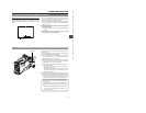
MODE switch
● Dubbing still images makes the images
coarser. In addition, noise may appear
in the sound.
Video component with DV Connector
DV connector
DV cable (VC-VDV204 (4P-4P), VC-VDV206 (4P-6P))
DV connector
Rear section of GY-DV5100
9. USING EXTERNAL COMPONENTS
E-65
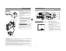
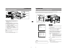
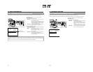
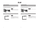
9-1 Connecting a Video Component with DV Connector
PHONES
DC OUT
DC IN
DV
INT
CH-1
CH-2
REAR AUDIO IN
TALLY
Connecting the GY-DV5100 to another video component equipped with DV I/O connector (IEEE1394 standard) using a DV cable
(optional) enables dubbing of digital signals with high picture quality and high-quality sound.
* GY-DV5100 is not capable of recording DV signals.
1.
Connect the units with the DV cable.
2.
Switch the DV/INT selector switch on the rear of the camera
to DV.
3.
Tu rn ON both units.
4.
Place the GY-DV5100 in the VTR MODE.
Press the MODE switch upward to turn on the VTR indicator.
5.
Insert the videocassettes.
GY-DV5100: Insert the recorded videocassette.
Recording unit: Insert the videocassette to be dubbed to.
6.
Press the PLAY button on the GY-DV5100 to start playback.
7.
Start recording on the recording unit.
For details, see the instructions to the unit used for recording.
8.
When dubbing is completed.
Stop recording on the recording unit, and then press the
STOP button on the GY-DV5100 to stop playback.
MEMO:
● Tu rn the camera off before switching DV/INT.
● The operation methods differ with the characteristics and specifications of the connected equipment. Even if connection is
possible, operation or data communication may sometimes be impossible to perform.
● If block noise appears or the sound falls out, try to disconnect and then connect the DV cable again, or turn the power to the
GY-DV5100 off and then on again.
● When connecting to a D-9 (digital-S) component with an IEEE1394 connection, the date and time data are not output from
the D-9 component. Also, the date and time data cannot be recorded on the D-9 component. When making an IEEE1394
connection with a D-9 component, install SA-DV60 on the device.
● If the power to the component connected to the DV connector is turned on, or the video input is changed, noise may appear
in the audio. When these operations have to be performed, reduce the sound volume of the audio component, speaker, etc.,
connected to the GY-DV5100 to a minimum.
● Recording may not be possible in some cases even if the recorder is equipped with a DV terminal.
When Using the GY-DV5100 as Playback Unit (Dubbing to Another Video)
MODE switch
● Dubbing still images makes the images coarser. In addition,
noise may appear in the sound.
Video component with DV Connector
DV connector
DV cable (VC-VDV204 (4P-4P), VC-VDV206 (4P-6P))
DV connector
Rear section of GY-DV5100
MONITOR
EDITSEARCH
FILTER
STATUS
SHUTTER
MENU
AUTO IRIS
BACK L
NORMAL
SPOT L
STRETCH
NORMAL
COMPRESS
FULL AUTO BLACK LOLUX
MODE
POWER
ON OFF
VTR
OPEN
VTR
CAM
1
3200K
5600K
5600K
5600K
ND
/
/
ND
2
.3
.4
1
8
1
64
CH-1
AUDIO INPUT
AUDIO SELECT
CH-2
CH-1 CH-2
FRONT
REAR
AUTO
MANUAL
AUDIO
LEVEL
CH-1 CH-2
PULL
OPEN
LCDBRIGHT DISPLAY
MODE
VTR
CAM
DV
INT
E
U