


AXIS Q7411 Video Encoder
Hardware Overview
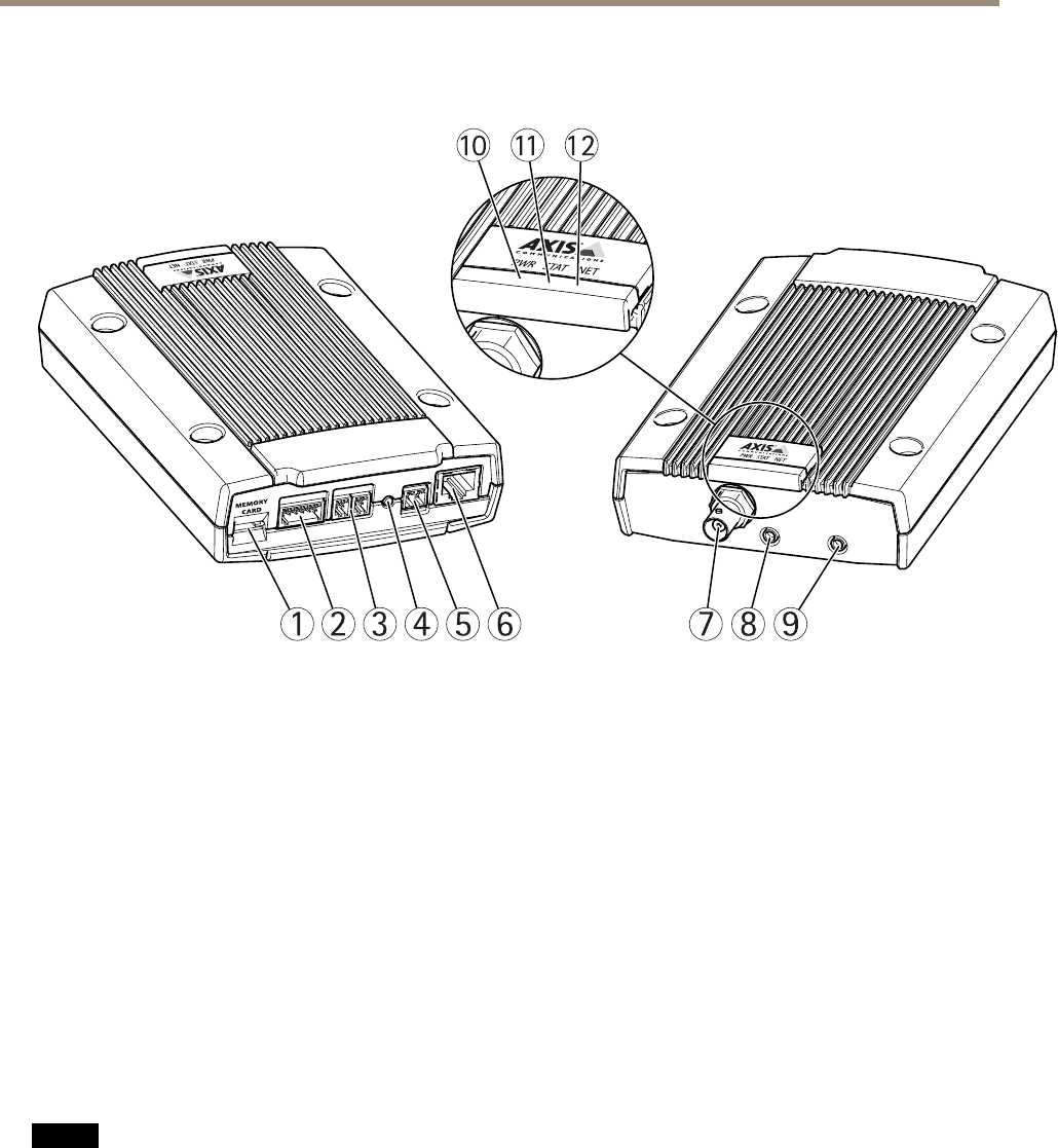
Hardware Overview
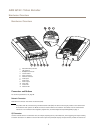
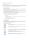
21 3 4 5 6 7 8 9
10
11 12
1
MicroSD memory card slot
2
I/O connector
3
RS485/422 connector
4
Control button
5
Power connector
6
Network connector
7
Video input
8
Audio input
9
Audio output
10
Power LED
11
Status LED
12
Network LED
Connectors and Buttons
For technical specications, see page 65.
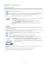
Network Connector
RJ45 Ethernet connector with Power over Ethernet (PoE).
NONO
NO
TICETICE
TICE
The product shall be connected using a shielded network cable (STP). All cables connecting the product to the network shall
be intended for their specic use. Make sure that the network devices are installed in accordance with the manufacturer’s
instructions. For information about regulatory requirements, see Electromagnetic Compatibility (EMC) on page 2 .
I/O Connector
Use with external devices in combination with, for example, tampering alarms, motion detection, event triggering, time lapse recording
and alarm notications. In addition to the 0 V DC reference point and power (DC output), the I/O connector provides the interface to:
7