


AXIS Q7411 Video Encoder
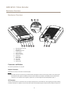
Hardware Overview
• Digital output – For connecting external devices such as relays and LEDs. Connected devices can be activated by the
VAPIX® Application Programming Interface, output buttons on the Live View page or by an Action Rule. The output will
show as active (shown under System Options > Ports & Devices) if the alarm device is activated.
• Digital input – An alarm input for connecting devices that can toggle between an open and closed circuit, for example:
PIRs, door/window contacts, glass break detectors, etc. When a signal is received the state changes and the input becomes
active (shown under System Options > Ports & Devices).
Power Connector
2-pin terminal block for power input. Use a Safety Extra Low Voltage (SELV) compliant limited power source (LPS) with either a rated
output power limited to ≤100 W or a rated output current limited to ≤5 A.
Audio Connector
The Axis product has the following audio connectors:
• Audio in (pink) – 3.5 mm input for a mono microphone, or a line-in mono signal.
• Audio out (green) – 3.5 mm output for audio (line level) that can be connected to a public address (PA) system or an
active speaker with a built-in amplier. A stereo connector must be used for audio out.
For audio in, the left channel is used from a stereo signal.
RS485/RS422 Connector
Two terminal blocks for RS485/RS422 serial interface used to control auxiliary equipment such as pan-tilt devices.
SD Card Slot
NONO
NO
TICETICE
TICE
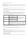
• Risk of damage to SD card. Do not use sharp tools or excessive force when inserting or removing the SD card.
• Risk of data loss. To prevent data corruption, the SD card should be unmounted before removal. To unmount, go to Setup >
System Options > Storage > SD Card and click Unmount.
This product supports microSD/microSDHC/microSDXC cards (not included).
For SD card recommendations, see www.axis.com
Control Button
For location of the control button, see Hardware Overview on page 7 .
The control button is used for:
• Resetting the product to factory default settings. See page 60.
• Connecting to an AXIS Video Hosting System service. See page 51. To connect, press and hold the button for about 3
seconds until the Status LED ashes green.
• Connecting to AXIS Internet Dynamic DNS Service. See page 51. To connect, press and hold the button for about 3 seconds.
LED Indicators
Note
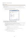
• The Status LED can be congured to ash while an event is active.
• The Status LED can be congured to ash for identifying the unit. Go to Setup > System Options > Maintenance .
8