


Security Escort | Technical Reference Manual | 3.0 System Menus
and Screens
EN | 19
Bosch Security Systems | 6/12 | 38947D
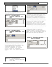
Insert New
Clicking this button displays a new
Edit Subscriber’s Advanced Features
Screen. This is used to enter a new
transponder to the database.
Edit Data
Clicking this button allows the
currently displayed transponder’s
database record to be edited.
Kill Transponder
Clicking this button deletes the
displayed transponder’s database
record. If the transponder is deleted.
its data is permanently deleted and
cannot be recovered.
Delete Point
Clicking this button deletes the
displayed point only from the displayed
transponder’s database record. If the
point is deleted, its data is
permanently deleted and cannot be
recovered.
Copy
Clicking this button copies the
displayed transponder’s database record
into a new transponder record. This
allows similarly configured
transponders to be programmed once,
then copied into a new record.
Note:
It is not possible to edit the
transponder ID itself. If this
should be necessary, the Copy button
can be used to produce another
Transponder Database entry
duplicating the first, but with the
transponder ID blank. The new
transponder ID can be entered, the
new data saved by using the Save
button, and the old transponder
entry can be deleted by using the
Kill Transponder button.
Print
Clicking this button prints the
displayed transponder’s database
record.
Beginning
Clicking this button changes the
displayed transponder to the first
transponder in the database.
Previous
Clicking this button changes the
displayed transponder to the previous
transponder in the database.
Next
Clicking this button changes the
displayed transponder to the next
transponder in the database.
End of File
Clicking this button changes the
displayed transponder to the last
transponder in the database.
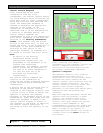
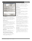
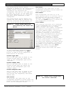
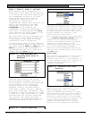
Mux Point Data
The lower portion of the Find
Transponder’s Database Screen provides
information on each of the devices
controlled by the transponder selected
in the Transponder field. Two digits
represent each receiver or alert unit
address; the first is the number of the
multiplex bus on which the device is
mounted (0 to 7) and the second is the
multiplex point address assigned to the
particular device. On each of the eight
multiplex busses up to eight devices
may be installed, but each device must
be assigned a unique multiplex point
address (0 to 7). More than one device
can have a particular multiplex point
address, but only if on different
busses. The multiplex point addresses
are assigned by switch settings on the
device (receiver or alert unit) circuit
boards. These multiplex point address
settings are also a part of the
Transponder Database. The multiplex
address shown in the Transponder
Database and the multiplex address set
on the device circuit board must agree.
The Transponder Setup Screen s used to
verify multiplex address settings.
It is a good idea to create an
entry in the Transponder
Database for each transponder
in the system before entering
the data for each device so
that all transponders appear in
the drop-down menus.
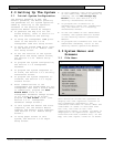
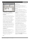
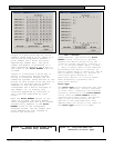
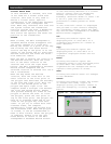
3.1.7 Creating a New Transponder Entry
The creation and modification of the
Transponder Database requires special
authority levels usually assigned only
to installation company personnel.
The Insert New button creates a new
Transponder Database Screen, ready for
entry of data.