


Security Escort | Technical Reference Manual | 3.0 System Menus
and Screens
EN | 43
Bosch Security Systems | 6/12 | 38947D
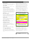
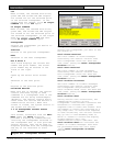
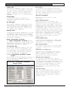
Device Type Map
Unlike all other types of map, the
device type map has two characters in
each possible device location. The
right most character indicates the
device type. A “5” indicates a
receiver, “3” indicates an alert unit,
and “7” indicates that the Transponder
Database shows a device in that
location but it is not currently
communicating with the transponder. The
left character indicates the following:
“0” (zero), the device is in its normal
state, “1”, the device is off normal,
and “x” there is a device connected to
the system at that address, but it is
not in the Transponder Database.
(Usually this results from an error
during data entry in the Transponder
Database.)
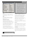
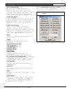
Not Responding Map
Requests a map of all the points that
are not responding (missing) to the
system on this transponder. The
Received Transmission Map button
produces a map display with one in the
locations corresponding to receivers
that are missing from the system. A “0”
(zero) indicates that the point is
responding. An “x” indicates there is a
device connected to the system at that
address, but it is not in the
Transponder Database.
Received Transmission Map
As a means of self-diagnosis, the
system software periodically reviews
the receivers, that have not received
an alarm or test transmission. This
list is printed as a part of the daily
System Status Report and is a tool for
assessing the health of the system. The
Received Transmission Map button
produces a map display with “1” in the
locations corresponding to receivers
which received transmissions. Each time
this map is read, the Received
Transmission Map image is cleared in
the transponder.
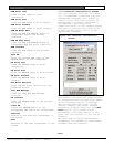
Strobe – Red LED Map
Requests a map of all the points on
this transponder that have their Strobe
– Red LED on. The Strobe – Red LED Map
button displays a map with “1” in the
locations corresponding to points which
have their outputs on. A “0” (zero)
indicates that the output is off.
Horn – Siren Map
Requests a map of all the points that
have their horn or sirens on, on this
transponder. The Horn – Sirens Map
button displays a map with “1” in the
locations corresponding to points which
have their outputs on. A “0” (zero)
indicates that the output is off.
Green LED Map
Requests a map of all the points on
this transponder that have their Spare
outputs – Green LED on. The Green LED
Map button displays a map with “1” in
the locations corresponding to points
which have their outputs on. A “0”
(zero) indicates that the output is
off.
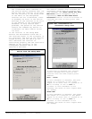
Jamming
Requests a map of all the receivers
that are currently reporting RF jamming
to the system. The Jamming button
displays a map with “1” in the
locations corresponding to receivers
that are reporting jamming. A “0”
(zero) indicates that the receiver is
not jammed.
Tamper
Requests a map of all the points that
are currently reporting a tamper
condition to the system. The Tamper
button displays a map with “1” in the
locations corresponding to points that
are reporting tamper. A “0” (zero)
indicates points that are not tampered.
AC Loss
Requests a map of all the alert units
that are currently reporting an AC
power failure to the system. The AC
Loss button displays a map with “1” in
the locations corresponding to alert
units that are reporting AC Loss.
Restarted
Requests a map of all the points that
are powered up or had a watchdog
failure to the system. The Restarted
button displays a map with “1” in the
locations corresponding to points that
are restarted.
Dropped
Requests a map of all the receivers
that have dropped one or more
receptions due to high traffic. The
Dropped button displays a map with “1”
in the locations corresponding to
receivers that dropped one or more
transmissions.