


Security Escort | Technical Reference Manual | 3.0 System Menus
and Screens
EN | 52
Bosch Security Systems | 6/12 | 38947D
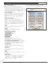
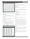
Transponder
Select the transponder for the
transmitting point and each receiving
point. They can be on the same or
different transponders.
Transmitting Point
Select the point (receiver) on the
selected transponder to generate the
transmissions.
Total Transmissions
The total number of times the
designated receiver transmitted the
test message.
Missed all Receivers
The total number of times that the test
transmission, was not heard by any of
the designated receivers.
Enable Rec
This box must be checked for this
receiver to monitor the test
transmissions.
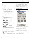
Point
Select the point (receiver) on this
transponder to monitor the test
transmissions.
Hits
The number of times this receiver
successfully heard the test
transmission.
Misses
The number of times this receiver
failed to hear the test transmission.
Highest
The left-hand box displays the highest
receive level at which the test
transmission was heard. The right-hand
box displays the greatest number of
packets heard from a single test
transmission.
Average
The left-hand box displays the average
receive level at which the test
transmission was heard. The right-hand
box displays the average number of
packets heard from a single test
transmission.
Lowest
The left-hand box displays the lowest
receive level at which the test
transmission was heard. The right-hand
box displays the least number of
packets heard from a single test
transmission.
Run Test
The test only runs when this box is
checked. To stop the test and retain
the test values, uncheck this box.
Spacing
This slows the test by forcing this
number of seconds between test
transmissions. Normally, this setting
is left at the default of 0.
Stop Test and Reset Counters
Clicking this button stops the test and
resets all values.
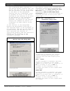
Close Screen, Does Not Stop Test
Clicking this button closes this screen
but does not stop the test from
running. Reopening the screen displays
the current progress of the test. The
test should not be left running unless
there is a specific need, as it
generates both RF and system traffic.
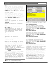
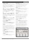
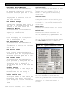
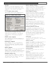
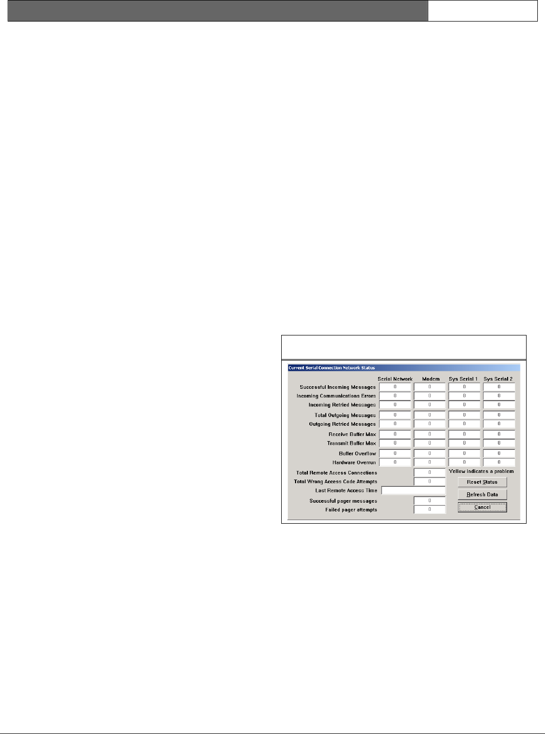
3.3.15 Network Status Screen
This screen shows the status of
communications on the network, modem,
and system serial ports.
Figure 500: Network Status Screen
Successful Incoming Messages
This value is the number of messages
that the system successfully received
on this communications port.
Incoming Communication Errors
This value is the number of messages
that the system detected errors in, on
this communications port. If displayed
in yellow, this value is more than 1.5%
of the Successful Incoming Messages.