


Security Escort | Technical Reference Manual | 3.0 System Menus
and Screens
EN | 24
Bosch Security Systems | 6/12 | 38947D
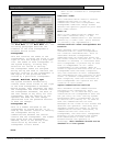
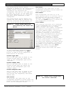
Location
This block contains the text to be
displayed on the Alarm Screen if this
receiver is one of those closest to the
alarm source. The description is
developed with the guidance of the
security personnel who must respond to
an alarm. It is vital that the
description be clear and unambiguous to
them.
To enter a location description, place
the cursor in the Location field, click
the mouse, and begin typing. Receiver
and alert unit location names are
important because they are used for
directing response to an alarm and aid
service personnel in identifying the
device in the event of a problem. The
Problem Reports displayed on the
central console and printed by the
hardcopy printer contain the device
location descriptions that are entered
in the Location field.
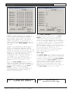
SA%
Security Escort Software version 2.03
and higher allow individual receiver
sensitivity to be set in the
Transponder Database. Receivers can be
adjusted from 50% to 149% of their
normal sensitivity. No physical
receiver changes or upgrades are
required. This setting should only be
changed if there are known location
accuracy problems in the area of this
receiver. Settings of 50 to 99
desensitize the receiver to 50% to 99%
of the actual received signal strength.
Settings of 1 to 49 increase the
sensitivity to 101% to 149% of the
actual received signal strength. Try
changing the sensitivity of receivers
one at a time while testing the alarm
location response. For example, if
alarms are being pulled towards a
particular receiver, lower its
sensitivity in 10% increments and
retest. If the area can be corrected
using this method, verify the
surrounding areas to make sure they
have not been adversely affected.
Generally, it is better if the
correction is done in small steps while
verifying the adjacent areas, rather
than trying to correct the entire error
in one step.
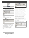
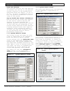
The SA% option is only available if the
Enable algorithm tweaks field is
checked in the System Preferences
Screen. Also in the Transponder
Database the Algorithm dropdown list
allows selection of Default, Classic,
Linear, Low, Medium, or Strong pull
location algorithms for each
transmitter. The point reporting the
best reception level determines the
actual algorithm used for the location
on any event. If programmed for
Default, the algorithm used is Linear
for points programmed as outdoor or
tunnel. All other points use Low. If
the point reporting the best reception
level is not programmed for the Default
algorithm, the location calculation
uses the algorithm programmed.
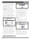
Map
Defines which bitmap to display for
this receiver or area when an alarm is
closest to it. The default map is 0,
which corresponds to bitmap MAP0.EDB
stored in the Security Escort sub-
directory. Map 1 is MAP1.EDB. There can
be 100 maps per Security Escort System
(0 to 99).
Video Switcher
Selects a system serial port programmed
in the Remote Setup Screen displaying
the most likely area the alarm is
located on the CCTV monitors near the
central console. The string activates a
macro in the video switcher that
selects the appropriate camera and
controls any required zoom and tilt
actions. Up to 40 characters can be
entered. Control characters can be
entered as [^][A] for control A.
Pager Group
The pager group that is paged if the
alarm location is determined to be in
this area.
Floor
Determines the floor number that this
area is defined for. The areas on
floors above and below this one can be
defined differently. For an area to be
selected when an alarm is received, the
location determined by the central
console must be located within the
defined area and must be located on the
designated floor.