


Security Escort | Technical Reference Manual | 3.0 System Menus
and Screens
EN | 20
Bosch Security Systems | 6/12 | 38947D
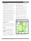
The System Design Layout Sheets
prepared in advance by the installation
manager should contain the necessary
information for assigning the
transponder name and ID, the comm port
or radio ID, as well as the names and
multiplex addresses for all receivers
and alert units connected to each
transponder.
The System Design Layout Sheets also
contain the text used to indicate the
receiver locations and designates the
alert units driven by each receiver.
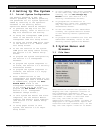
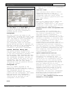
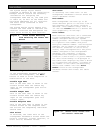
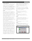
Figure 9: Blank Screen Resulting
from Selecting the Insert New
Button
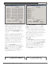
3.1.8 Setting Receiver Parameters
If the Transponder Database already
contains the transponder, the Edit
button is used to allow completion or
modification of the data.
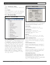
Trouble Type Text
This is the text that is shown in the
Trouble Screen when the remote key
input on the transponder goes active
(shorted).
Trouble Tamper Text
This is the text that is shown in the
Trouble Screen when the remote key
input on the transponder goes into
trouble (open).
Trouble Response Text
This is the text that is shown in the
Trouble Screen as the response test.
The actions the responding individual
should take.
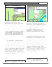
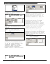
Show Points
If selected, the lower half of the
Transponder Database’s Screen shows the
point’s (receiver, virtual receiver, or
alert unit’s) database values.
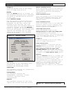
Show Areas
If selected, the lower half of the
Transponder Database’s Screen shows the
area’s database values.
Area Number
Each Transponder can have up to 80
areas defined (prior to version 2.04 of
the software only 40 areas could be
defined). Area numbers range from 0 to
79. Use the Locate button to define the
area graphically on the map.
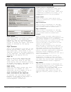
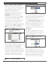
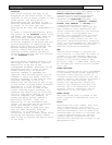
Point Number
Each receiver and alert unit connected
to the transponder has a unique point
number assigned during the system
design process. This number corresponds
to a specific bus number and point
multiplex address number. The multiplex
address, set by means of switches on
the device (receiver or alert unit)
itself, must correspond with the point
number assigned in the Transponder
Database. For instance, a device
programmed with multiplex address
location 3 and on bus 5 is point number
29. This relationship is displayed in
the table that displays anytime a ? box
is clicked with the mouse. Clicking on
any number in the table automatically
enters that number into the Point
Number field on the Transponder
Database Screen and closes the table
screen.
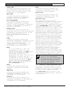
Figure 10: Select Point Screen with
"All Points" Selected