


100 en | Appendix VOT-320
DOC | V4.5 | 2010.09 Installation and Operating Manual Bosch Sicherheitssysteme GmbH
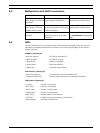
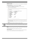
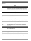
Serial interface (upper 6-pin terminal block)
The pin assignment of the serial interface depends on the interface mode used (see
Section 5.33 Advanced Mode: COM1, page 68).
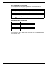
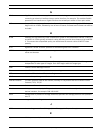
Relay and alarm (lower 6-pin terminal block)
Connect each alarm input to a ground contact (GND) on the upper 6-pin terminal block when
connecting alarm inputs.
Pin No. Contact RS-232 mode RS-422 mode RS-485 mode
1 RXD RxD (receive data) RxD+ (receive data plus) Data+
2 CTS CTS (clear to send) RxD– (receive data minus) Data–
3 RTS RTS TxD+ (transmit data plus) Data+
4 TXD TxD (transmit data) TxD– (transmit data minus) Data–
5GNDGND (ground) — —
6GND— — —
Pin No. Contact Function
1 R1 Relay output 1
2 R1 Relay output 1
3 R2 Relay output 2
4 R2 Relay output 2
5 IN1 Input alarm 1
6 IN2 Input alarm 2