


VOT-320 Installation | en 19
Bosch Sicherheitssysteme GmbH Installation and Operating Manual DOC | V4.5 | 2010.09
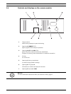
4.3 Connections
Network
You can connect the VOT-320 to a 10/100 Base-T network using a standard UTP category 5
cable with RJ45 plugs.
1. First crimp the wires according to the EIA/TIA standard you are using.
2. Connect the VOT-320 to the network via the RJ45 socket on the back of the camera
module.
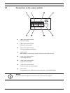
Data interface
The bidirectional data interface is used to control units connected to the VOT-320, such as
pan/tilts that are not connected directly to the P/T connections (see Section Pan/tilt
connection, page 20). The connection supports the RS-232, RS-422 and RS-485 transmission
standards.
The VOT-320 offers the serial interface via the upper 6-pin terminal block (see
Section 8.8 Terminal blocks, page 99).
The range of controllable equipment is expanding constantly. The manufacturers of the
relevant equipment provide specific information on installation and control.
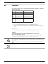
Pin EIA/TIA-568-A EIA/TIA-568-B
1 white/green white/orange
2 green orange
3 white/orange white/green
4 blue blue
5 white/blue white/blue
6 orange green
7 white/brown white/brown
8 brown brown
CAUTION!
Please take note of the appropriate documentation when installing and operating the unit to
be controlled.
The documentation contains important safety instructions and information about permitted
uses.
NOTICE!
A video connection is necessary to transmit transparent data.