


VOT-320 Appendix | en 99
Bosch Sicherheitssysteme GmbH Installation and Operating Manual DOC | V4.5 | 2010.09
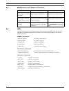
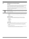
8.8 Terminal blocks
The VOT-320 offers three pairs of terminal blocks arranged in an upper (U) and lower (L) row:
– X-block: 2-pin blocks for power supply and window defroster
– Y-block: 5-pin blocks for PT control
– Z-block: 6-pin blocks for serial data transmission, relay outputs and alarm inputs
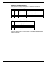
Power supply (upper 2-pin terminal block)
Connect the power supply to the upper 2-pin terminal block (UX1 and UX2).
Window defroster (lower 2-pin terminal block)
The window defroster by default is connected to the lower 2-pin terminal block (LX1 and LX2)
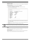
PT control (upper and lower 5-pin terminal blocks)
Pan/tilts are connected to the Y-block as follows:
Bosch LTC 9418/11 and LTC 9418/21 are recommended as pan/tilts. For additional
information and wiring diagrams refer to the corresponding manuals.
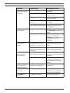
Row Pin No. Contact Function
U 1 Pan Right Panning to the right
U 2 Pan Left Panning to the left
U 3 P/T Common Return path for P/T motors
U 4 Pan Position Analog feedback on position
U 5 Tilt Position Analog feedback on position
L 1 Tilt Up Tilting up
L 2 Tilt Down Tilting down
L 3 P/T Common Return path for P/T motors
L 4 PP Return (-) Supply for analog feedback of position
L 5 PP Supply (+) Supply for analog feedback of position
CAUTION!
Please take note of the appropriate documentation when installing and operating the unit to
be controlled.
The documentation contains important safety instructions and information about permitted
uses.