


5
MODEL 54e pH/ORP SECTION 2.0
INSTALLATION
SECTION 2.0
INSTALLATION
This section is for installation of the controller.
WARNING
All electrical installation must conform to the
National Electrical Code, all state and local
codes, and all plant codes and standards for
electrical equipment. All electrical installations
must be supervised by a qualified and respon-
sible plant electrician.
2.1 LOCATING THE CONTROLLER
Position the Model 54e pH/ORP controller to minimize
the effects of temperature extremes and to avoid
vibration and shock. Locate the controller away from
your chemical process to protect it from moisture and
fumes.
Select an installation site that is more than 2 ft from
high voltage conduit, has easy access for operating
personnel, and is not exposed to direct sunlight.
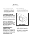
2.2 UNPACKING AND INSPECTION
Inspect the exterior of the shipping container for any
damage. Open the container and inspect the controller
and related hardware for missing or damaged parts.
If there is evidence of damage, notify the carrier im-
mediately. If parts are missing, contact Rosemount
Analytical customer support.
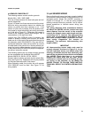
2.3 MECHANICAL INSTALLATION
2.3.1 Mounting the Controller
The Model 54e pH/ORP controller may be supplied
with a mounting bracket accessory. If you use the
mounting bracket on wall or pipe installations, avoid
mounting on pipes which vibrate or are close to the
process. The bracket may be modified to mount the
controller on I-beams or other rigid members. You can
also fabricate your own bracket or panel mount the
controller using the bracket as an example.
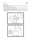
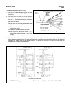
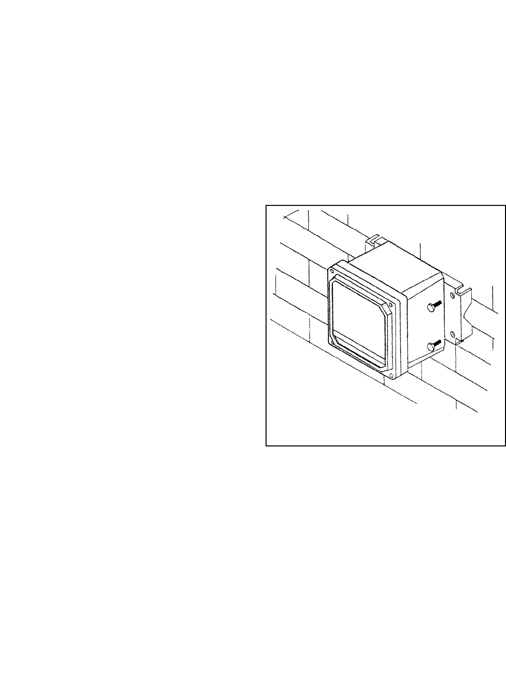
2.3.2 Wall or Surface Mounting:
1. Mount the bracket to the controller using the sup-
plied four screws as shown in Figure 2-2.
2. Mount controller mounting bracket to wall using
any appropriate fastener such as screws, bolts,
etc (see Figure 2-1 below).
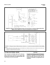
2.3.3 Pipe Mounting:
1. Attach the mounting bracket to the rear of the con-
troller and tighten the four screws as shown in
Figure 2-2.
2. Place supplied U bolts around the mounting pipe
and through the pipe mounting bracket and
mounting bracket. Tighten the U bolt nuts until the
controller is securely mounted to the pipe.
FIGURE 2-1. Wall Mounting