


1
MODEL 54e pH/ORP SECTION 1.0
DESCRIPTION AND SPECIFICATIONS
SECTION 1.0
DESCRIPTION AND SPECIFICATIONS
1.1 GENERAL DESCRIPTION
The Model 54e pH/ORP analyzer/controller monitors
and controls pH in chemical processes used in many
industries. This manual's sections and appendices
cover the system's configuration, calibration, and
maintenance, and provides a troubleshooting guide.
All adjustments to the current outputs, alarm relays,
and calibration of the pH and temperature inputs can
be made using the controller's membrane keypad.
1.2 DESCRIPTION OF CONTROLS
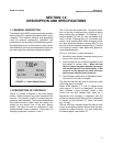
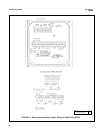
Figure 1-1 shows a diagram of the main display
screen. Similar diagrams are used throughout this
manual. The primary variable is continuously dis-
played in large numerals. The process temperature
and primary current output value are always dis-
played on the second line of the main display
screen. The third line can be configured to read
several different items, as desired. In this case, it is
displaying setpoints for alarms 1 and 2.
The F1-F4 keys are multifunction. The active opera-
tion for that key is displayed as a label just above
each function key as needed. For example, F1 is
usually labeled Exit and F4 may be labeled Edit,
Save, or Enter. Pressing Enter 4 will access sub-
menus, while pressing Edit allows changing values
and Save stores the values in memory. Esc 3 can
be used to abort unwanted changes. Exit 1 returns
to the previous screen. Other labels may appear for
more specialized tasks.
The up t and down b keys are used to:
1. Move the cursor (shown in reverse video) up and
down on the menu screens.
2. Scroll through the list of options available for the
field shown in reverse video. When the last
item of a menu has been reached, the cursor
will rest on the third line of the display. If the
cursor is on the second line, there are more
items to see with the down arrow key.
3. Scroll through values when a highlighted numer-
ical value is to be set or changed.
The right and left keys are used to move the cursor
to the next digit of a number.
Green LEDs (labeled 1, 2, and 3) indicate when
alarm relays 1, 2, and 3 are energized. The fourth
relay indicates a fault condition. When a fault
occurs, the red LED (labeled FAIL) lights up, a
descriptive error message is displayed, and the
action of the outputs and relays will be as described
in Section 5.6 and Section 5.7 under fault value
(e.g. 22 mA).
The red LED also indicates when the interval timer
routine is activated and when the time limit has been
reached on a feed limit timer. For more information
on these subjects, see Section 5.7.
FIGURE 1-1. Main Display Screen
7.00
pH
26.2°C. 12.0 mA
AL1: 0.0 AL2: 14.0