


54
MODEL 54e pH/ORP SECTION 7.0
SPECIAL PROCEDURES AND FEATURES
SECTION 7.0
SPECIAL PROCEDURES AND FEATURES
This section covers features of the Model 54e
pH/ORP controller that are used less frequently.
Use of the features outlined in the appendix is
optional.
Special procedures and features outlined in this
appendix include the following:
• Password Protection
• Temperature Slope Calculation
• Temperature Sensor
• Reference Temperature
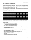
• Controller Mode Priority
• PID Control
Before using this section, you should become familiar
with the basic Theory of Operation of the controller as
outlined in Section 6.0, the keypad functions in Section
1.0, and the List of Settings Table and configuration
procedures outlined in Section 5.0.
As with all the settings in your Model 54e pH/ORP, the
first step to configuration is obtaining a good under-
standing of how the feature works, before determining
the values of the settings to achieve the desired con-
trol. This appendix provides more background for
deciding on the appropriate settings. Configuring the
settings is done using the instructions in this appendix
and Section 5.0, Software Configuration.
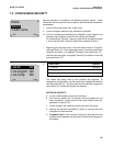
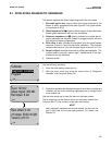
7.1 PASSWORD PROTECTION
Your Model 54e pH/ORP can be programmed so that a
3-digit password must be entered before any changes
in the configuration are allowed. This protects your
controller from tampering by unauthorized users. There
are three levels of password access, Level 1 (calibra-
tion only), Level 2 (lockout of Configure Menu), and
Level 3 (total access). Password privileges for each
level are described below.
If password protection is not desirable, you can config-
ure all security codes to be 000. This will leave the con-
troller unlocked so the configuration can be changed
without entering a password. The controller is shipped
from the factory with the password set at 000.
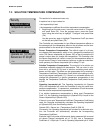
Level 1 - 3 Password Privileges
Level 1 access is usually given to an operator who
simply needs to calibrate during the course of normal
operation. A separate section of the manual contains
operating procedures normally used by this type of per-
sonnel. Level 1 restricts the operator from changing the
major control mode configuration by preventing access
to the Program Menu.
The Level 1 user can do the following:
1. Access Diagnostic Variables (Section 8.1).
2. Zero the controller in air (Section 4.3).
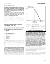
3. Enter the Temperature Slope (Section 4.4).
4. Change Temperature Compensation from Auto to
Manual and select a temperature (Section 4.7).
5. Calibrating pH and Temperature readings (Section
4.1 and Section 4.6).
A Level 2 user can do all of the above and:
1. Change control setpoints for PID current outputs
(Section 5.1).
2. Change alarm setpoints for normal and TPC
alarms (Section 5.2).
3. Rerange both 4-20 (or 0-20) mA outputs
(Section 5.3).
4. Manually test both outputs and all 4 alarm relays
for operation.
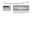
A Level 3 user has total access to the Configure Menu
and can make any changes that are deemed neces-
sary.
These privileges should be given only to an indi-
vidual who fully understands the controller, the
process and the potential effects of modifying the
setup.
An individual with no password access privilege can
only view the main display, containing conductivity,
temperature, current output 1, and the lower line dis-
play items configured in Section 5.5.
NOTE
You must have level 3 access to
change any security code.