iii
MODEL 54e pH/ORP TABLE OF CONTENTS
TABLE OF CONTENTS (CONTINUED)
LIST OF FIGURES
Figure No. Title Page
1-1 Main Display Screen............................................................................. 1
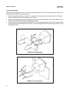
2-1 Wall Mounting....................................................................................... 5
2-2 Pipe Mounting....................................................................................... 6
2-3 Panel Mounting..................................................................................... 6
3-1 Power Input and Relay Output Wiring for Model 54e pH/ORP............. 8
3-2 Sensor Wiring Photo............................................................................. 9
3-3 Sensor Wiring Diagram ........................................................................ 10
3-4 Cable Dressing ..................................................................................... 11
3-5 Wiring for Sensors that have Solution Grounds ................................... 11
3-6 Wiring for Sensors without Solution Grounds Directly to Analyzer....... 12
3-7 Wiring for Sensors without Solution Grounds to a Junction Box .......... 12
3-8 Wiring to Model 399-14 ........................................................................ 13
5-1 Menu Tree ............................................................................................ 25
5-2 Interval Timer Examples ....................................................................... 41
6-1 Time Proportional Control..................................................................... 47
6-2 The Process Reaction Curve................................................................ 52
8-1 Theoretical pH vs. Millivolt Values at 25°C (77°F) ................................ 62
8-2 Junction Box Preamplifier Check.......................................................... 65
8-3 Controller Preamplifier Check............................................................... 65
A-1 Outline of Menu Levels for ORP........................................................... 74
About This Document
This manual contains instructions for installation and operation of the Model 54epH
pH/ORP HART Analyzer/Controller. The following list provides notes concerning all
revisions of this document.
Rev
. Level Date Notes
0 5/00 This is the initial release of the product manual. The manual
has been reformatted to reflect the Emerson documentation
style and updated to reflect any changes in the product offering.
0 11/01 Added trip output infor & fixed panel dimension reference.
A 3/02 Updated multiple drawings & added menus.
B 7/02 Fixed setpoint example screen on page 27.
C 4/03 Updated CE info.
D 7/04 Fixed power and weight specs on page 2.
E 3/05 Updated recommended sensors on page 3.
F 4/05 Added note re ordering circuit board stack on page 69.
G 2/06 Updated Figure 1, Menu tree.


