


46
MODEL 54e pH/ORP SECTION 6.0
THEORY OF OPERATION
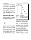
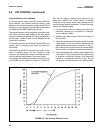
A new glass electrode has an impedance of approxi-
mately 200 megohms As it ages, this value typically
increases over time because lithium ions (which carry
current) in the glass are slowly depleted by the
process. If an electrode cracks, the impedance drops
sharply, usually to below 5 MΩ.
The following Diagnostic Checks are possible with the
Model 54e pH/ORP:
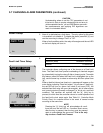
Cracked Glass Diagnostic. One way to tell that you
have a broken or cracked glass electrode is that the
controller will read a constant value (usually between
5.0-7.0 pH) in any process or buffer. The other way is
to note the impedance value. The controller can be
configured to generate a fault when the glass imped-
ance drops below a setpoint. When a crack occurs, the
controller will indicate that the electrode is broken.
NOTE
A broken electrode may not be detected above
70°C (158°F).
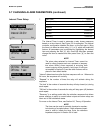
Old Glass Diagnostic. This diagnostic is used for pro-
gramming the high impedance limit. For example, if the
set point is 1000 megohms, and the impedance rises
above this value, the controller will go into a fault mode.
The electrode is either worn out, severely coated, or
not immersed in the process fluid..
Calibration Warning. Under this diagnostic you can
select the percent increase in impedance before a cal-
ibration warning fault appears. It is recommended to
keep this feature disabled.
High Reference Impedance. The reference is also
continuously checked. High values indicate a plugged
liquid junction or a coated sensor. The setpoint can be
adjusted depending on the sensor used. Always set
this value above the value for a new clean sensor.
You may also get this fault if:
1. The sensor becomes excessively coated.
2. The sensor is not immersed in the process
Typical set points:
1. 1000 Megohms for old glass diagnostics.
2. 10 Megohms for cracked glass.
3. 0 Megohms for calibration warning (disabled)
4. 40 Kohms for high reference impedance.
NOTE
See Section 5.8 for instructions on chang-
ing these setpoints.
6.3 INTERVAL TIMER
The interval timer may be used for periodic sensor
cleaning or periodic process adjustment (see Section
5.7 for procedure).
The interval timer settings are:
1. Timer - Enables/disables the interval timer.
2. Interval - the time period between cycles.
3. Repeats - the number of relay activations per
cycle.
4. On time - the time period of one relay
activation.
5. Off time - the time period between two or more
relay activations.
6. Recovery - the time period following the final relay
activation.
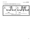
The cycle begins at the Interval time when the Switch
is turned on. When the Interval time has expired the
analyzer activates hold mode and the relay is activated
for the On time period. If the number of Repeats is
greater than one, the relay is deactivated for the Off
time period and reactivated for the On time period for
the number of relay activations selected. When the
final relay activation is complete the relay is deactivat-
ed for the Recovery time period. Note that no Off time
period follows this last relay activation. When the
Recovery time period expires the Hold mode deacti-
vates, and the cycle repeats, beginning with the
Interval time.
Typically, the interval timer is configured with a long
Interval, several Repeats of fairly short On times, fairly
short Off times and a Recovery time which allows the
process to stabilize. Setting Interval to zero results in
continuous pulsing and setting Off time to zero will
cause a single pulse equal to [On time x Repeats].
High reference impedance can be used to trigger timer
activation. In this case, the interval time is used only to
allow the analyzer time to determine whether the refer-
ence impedance has exceeded the reference imped-
ance setpoint. If the reference impedance setpoint is
exceeded, the timer cycle will begin. This is an ideal
way to start a cleaning cycle in a dirty application.
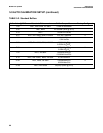
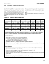
Note that the hold mode supersedes the Timer State. If
the hold mode is on, the present interval time continues
to expire and once expired the interval timer is sus-
pended until the hold state is removed. For more infor-
mation on Controller Mode Priority, see Table 6-1.