


60
MODEL 54e pH/ORP SECTION 8.0
TROUBLESHOOTING
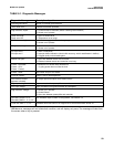
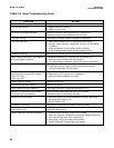
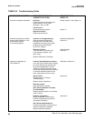
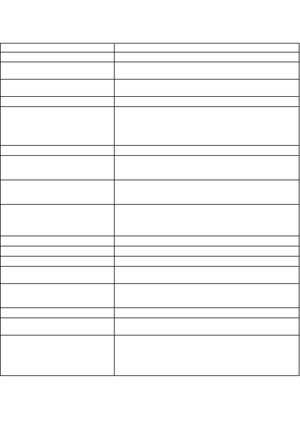
TABLE 8-2. Quick Troubleshooting Guide
SYMPTOM ACTION
pH reading won't change in different buffers. Clean the electrode, check wiring. Replace electrode.
"Cracked glass failure". 1. Replace electrode if cracked.
2. Check wiring for short.
pH sensor has sluggish response. Clean the electrode; if still sluggish soak in 1% HCl for 1 hr.
Replace electrode if not rejuvenated by the HCl soak.
"Old glass warning". Check sensor in buffers; replace if calibration unsuccessful.
"Lo or Hi slope error". 1. Verify internal preamp switch is in the appropriate position.
2. Improper buffer calibration: check buffer accuracy; wait for reading
to stabilize;
3. Clean the electrode; if fault persists; replace electrode.
4. If new electrode doesn't resolve the fault; replace preamp.
"Calibration warning". Check sensor in buffers; replace if calibration unsuccessful.
"Wait" flashing continuously; won't stabilize 1. Readjust stabilization pH or time for Auto Cal (Section 5.9)
during Auto Buffer Calibration. 2. Clean the sensor and retry Auto Cal in buffers.
3. Try a Manual Buffer Calibration. (see Section 5.9 for configuration)
Calibrates in buffers but not in the process 1. Verify process reading to be correct
2. Possible ground loop. Make sure that the shield wires do NOT
touch grounded metal. (Process noise).
Incorrect temperature reading. 1. Standardize the temperature
Suspected temp. compensation problem. 2. Verify sensor's RTD resistance vs. temperature
"Temp. error high" 3. Verify temperature reading to be correct
"Temp. error low"
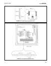
Display segments missing. Replace Display board.
Analyzer locks up; won't respond. Replace CPU board.
Erratic display and relays chattering. Check alarm set points, configuration (Sections 5.2, 5.7)
Analyzer not responding to key presses. Verify and clean ribbon cable connection on CPU board.
Key press gives wrong selection. Replace enclosure door/keyboard assembly.
Wrong or no current output. 1. Verify that output is not being overloaded (max load is 600 ohms)
2. Rerange outputs (Section 3.3)
3. Replace Power board
No display or indicators. Verify that the removable fuse module is securely seated.
Alarm relay closure problems. Check Power board.
Power board cut-off. Replace the Power board.
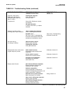
Sensor diagnostics faults keep appearing 1. Calibrate sensor in buffers; replace if unsuccessful
2. Check the diagnostic variables for inappropriate settings (Section 5.8)
3. Turn analyzer diagnostics "OFF" (Section 5.8)
4. Verify proper wiring and preamp switch position.
5. Perform Systematic Troubleshooting procedures.