


9
MODEL 54e pH/ORP SECTION 3.0
WIRING
pH SENSOR COMPATIBILITY
The following sensors contain solution grounds:
Models 381+, 385+, 396P, 396R
The use of these sensors will allow both glass and ref-
erence diagnostics.
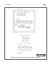
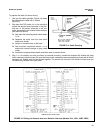
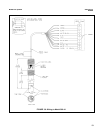
Figure 3-3 shows how these sensors should be wired.
Note that wiring connections depend on whether the
sensor (or junction box) has a preamp or not. If the
sensor (or j-box) has a preamp, then the preamp loca-
tion jumper is moved accordingly and wiring connected
as on the left of Figure 3-3. Otherwise, the jumper is
moved to the "analyzer" position and wiring for TB1 is
connected as on the right hand side.
Junction box (P/N 23550-00) wiring for sensors that
contain a preamp is strictly point to point. All sensor
leads are run to the junction box and carried through by
the extension cable (P/N 9200273). Only use this rec-
ommended extension cable and be careful to connect
all cable leads in the junction box. Sensors without pre-
amps that require cable extension should be wired up
to the junction box (P/N 23555-00) as per the appropri-
ate sensor instruction manual.
The following sensors do not contain solution grounds
but are compatible with the Model 54e pH/ORP:
Models 389-02-54, 396-54, 397-54, 399-09
Sensors without solution grounds must be wired differ-
ently (see Figure 3-6). Diagnostics will only be possible
on the glass electrode side of the sensor.
When extending cable, the junction box with preamp
(P/N 23555-00) must be used. See Figure 3-7 for
wiring details.
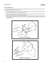
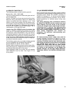
3.5 pH SENSOR WIRING
Be sure that the pH sensor has been properly installed
and mounted. Wire the sensor to the junction box (if so
equipped) and/or Model 54e pH/ORP according to
Figures 3-5 through 3-7, or use the wiring diagram
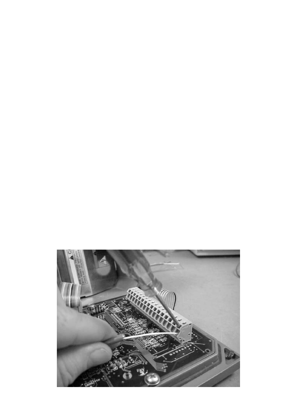
drawing included inside the controller. Use a narrow-
bladed screwdriver to facilitate sensor wiring (see
Figure 3-2).
The wiring diagrams show connections between
the Model 54e pH/ORP and the junction box used
where distance from the sensor to the controller
exceeds the integral sensor cable length and inter-
connecting wire is required. The interconnecting
sensor wire recommended is P/N 9200273. Use of
this cable provides EMI/RFI protection and com-
plete sensor diagnostics (for sensors so
equipped). The maximum interconnecting wire
length is 500 ft.
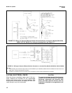
IMPORTANT
All interconnecting sensor cable ends must be
properly dressed, as shown in Figure 3-4, to pre-
vent the individual sensor and shield wires from
shorting. All shields must be kept electrically sep-
arate all the way back to the terminals on the Model
54e pH/ORP. Check that there is no continuity
between the shield wires and any other sensor
conductors or shields prior to connecting the sen-
sor wiring to the terminals on the Model 54e
pH/ORP. FAILING TO FOLLOW THESE INSTRUC-
TIONS WILL RESULT IN CONTROLLER MALFUNC-
TION.
FIGURE 3-2. Sensor Wiring Photo