


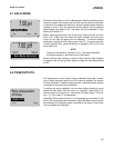
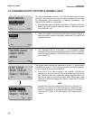
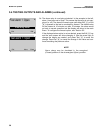
Test output 1: 10.00 mA
Esc Test
Test output 1: 10.00 mA
Simulating output1
Exit Edit
MODEL 54e pH/ORP SECTION 5.0
SOFTWARE CONFIGURATION
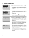
5.4 TESTING OUTPUTS AND ALARMS
This section describes how the current outputs and alarm relays can be
manually set for the purposes of checking devices such as valves,
pumps, or recorders.
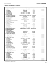
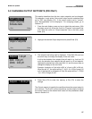
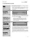
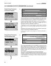
1. From the main menu, move the cursor down to "Program" and press
Enter 4. On this display, move the cursor to "Simulated tests" and
press Enter 4.
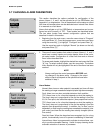
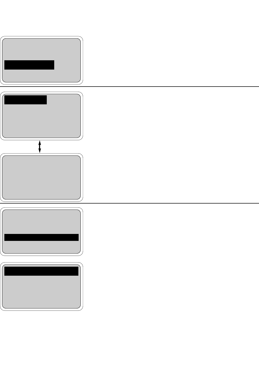
2. At this point there are six separate screens for testing each of the
current outputs and each of the alarm relays. Highlight the desired
item by pressing the arrow b t keys as needed.
When the desired item is highlighted, press Enter 4 to continue.
Go to step 3a for outputs and 3b for alarms.
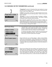
NOTE
A cautionary message will appear to warn that the out-
put or alarm that was selected will be changed by the fol-
lowing action. Be sure to alert plant personnel that
these changes are simulated and do not represent a
change in the actual process. Press Enter 4 to contin-
ue or Abort 1 to cancel the simulation.
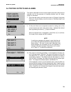
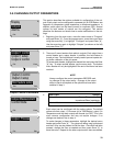
3a. The output is now being simulated. In the example to the left, out-
put 1 has been set to 10.00 mA. The output will remain at 10.00 mA
until either Exit 1 (or Edit 4 see below) is pressed or the test is
concluded by timeout. The default value for the timeout is 10 min-
utes, so after 10 minutes, the output would go back to normal oper-
ation. To configure the timeout option, see Section 5.5.
If the displayed current is not the desired value, press the Edit 4
key and the next screen will allow changing the value. Use the arrow
keys to change the display as needed, and press Test 4 to use that
value. Press Esc 3 to cancel the change in the value and contin-
ue simulating the previous current.
Alarm setpoints
Output setpoints
Simulated tests
Exit Enter
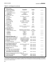
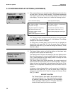
Test output 1
Test output 2
Test alarm 1
Exit Enter
Test alarm 2
Test alarm 3
Test alarm 4
Exit Enter
29