


MODEL 54e pH/ORP SECTION 3.0
WIRING
SECTION 3.0
WIRING
3.1 GENERAL
WARNING
All electrical installation must conform to the
National Electrical Code, all state and local
codes, and all plant codes and standards for
electrical equipment. All electrical installations
must be supervised by a qualified and respon-
sible plant electrician.
NOTE
Wire only the analog and alarm outputs
required for your application. Be sure to read
the warning at the beginning of Section 2.0.
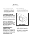
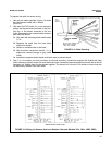
The Model 54e pH/ORP has five access holes in the bot-
tom of the instrument housing which accept ½-in. strain
relief connectors or conduit fittings. Be sure to seal any
unused access holes. As you face the front of the unit,
the rear openings are for input power, and alarm relay
signals. The opening on the front left is for sensor wiring
only (DC). The front right is for analog output wiring.
NOTE
For best EMI/RFI protection, the output cable
should be shielded and enclosed in an earth
grounded, rigid, metal conduit. Connect the
output cable's outer shield to the earth ground
connection on TB2 (Figure 3-1)
3.2 POWER INPUT WIRING
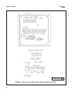
Figure 3-1 depicts the wiring detail for the Model 54e
pH/ORP. Code -01: connect AC power to TB3, termi-
nals 1 and 2 for 115 VAC (terminals 2 and 3 for 230
VAC). Code -02: connect DC power to TB3 terminals 1
and 2. Connect earth ground to the nearby ground lug.
A good earth ground is essential for proper operation of
the controller. Be sure to provide a means of discon-
necting the main power to the controller.
CAUTION
Do not apply power to the controller until all
electrical connections are made.
WARNING
Electrical connections to this equipment
must be made in accordance with the cur-
rent National and Local Electrical Codes in
effect for the installation location.
3.3 ANALOG OUTPUT WIRING
The analog output wiring consists of two 4-20 mA sig-
nals: output one from terminals 4 and 5, output 2 from
1 and 2 on TB2, as shown in Figure 3-1. These signals
can be used for chart recorder, computer monitoring, or
PID control output. The analog outputs can be pro-
grammed for 4-20 mA or for 0-20 mA, direct or reverse
acting. Current output 1 includes superimposed HART
(code -09 only).
3.4 ALARM RELAY OUTPUT WIRING
The controller has 3 "dry" alarm relay contacts which are
normally open. Alarm 1 is across terminals 4 and 5 on
TB3. This alarm is typically used to control the pump in a
chemical feed system. Alarm 2 across terminals 6 and 7
on TB3 is usually used to operate a light or horn as a
means of alerting the chemical process operator when
pH/ORP is outside the control range. Alarm 3 is across
terminals 8 and 9 on TB3. All 3 of these alarms may be
activated on pH/ORP or temperature. They can also be
used to control other pumps or valves provided they are
programmed to do so. Refer to Section 5.0 to set up these
functions.
All three alarm contacts on the Model 54e pH/ORP are
rated for a maximum of 3 A (1.5A, 230 VAC, inductive
load). If your associated pump or valve exceeds this,
use a separate contact or relay rated for the external
device.
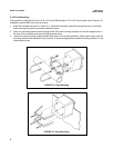
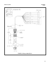
To use a contact output to control a pump, valve, or
light, the contact must be wired into a circuit together
with a source of power for the device to be controlled.
The power can be jumpered from the main power into
the controller and the circuit can be wired as shown on
the wiring diagrams, Figure 3-1.
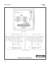
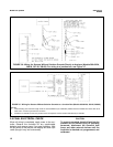
PREAMPLIFIER SELECTION
The pH sensor signal requires a preamplifier at some
point in the measuring circuit. The preamp can be in-
side the sensor, in the junction box, or in the controller.
To allow for these options, the Model 54e pH/ORP has
a jumper selectable preamp mounted on the CPU cir-
cuit board (Figure 3-3). The jumper is placed in the
"analyzer" position when there is no preamp in the sen-
sor (or junction box). Generally, this jumper is in the
"sensor" position.
7