


MODEL 54e pH/ORP SECTION 8.0
TROUBLESHOOTING
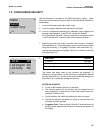
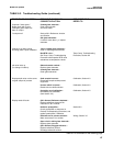
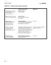
8.2 TROUBLESHOOTING GUIDELINES
NOTE
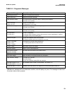
To clear any Fault message, press the
2 key.
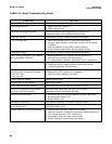
If no specific error message is being displayed, the fol-
lowing procedure can identify the specific problem.
The only sure way to diagnose sensor related condi-
tions is to isolate the pH sensor from the process, im-
merse the sensor in a pH buffer solution, and observe
the controller response.
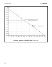
For any given pH value, the millivolt reading at the
controller should be approximately that shown in
Figure 8-1, Theoretical pH vs. Millivolt Values.
Therefore, one way to check the controller is to see if
the incoming millivolt signal corresponds to the proc-
ess pH or the pH of a test buffer solution (see Figure
8-1). The displayed pH value can be changed by stan-
dardizing, but the millivolt value (displayed under
"Diagnostic variables", see Section 8.1) will always be
the exact incoming value. Another good check of the
controller is to check the slope obtained after per-form-
ing the two-point calibration with two different buffer
solutions, as described in Section 3.
If the controller reads correctly when the sensor is
removed from the process and isolated in a container
of buffer solution, then the sensor and controller are
most likely functioning correctly. The problem is
caused by something in the process such as:
• Sensor "seeing" poorly mixed, non-homogeneous
solution.
• Sensor located too close to chemical feed lines or
heat sources.
• Air bubbles entrained in the process or entrapped
around the sensor.
• Voltage on the process due to static electricity
buildup, improperly grounded recirculation pump
motors, or some other electrical source.
• A ground loop caused by improper sensor wiring,
as outlined in Installation, Section 2.
• A source of electrical noise which only takes effect
when the sensor is immersed in the process.
Most of these problems can be eliminated by either
moving the sensor or providing proper grounding.
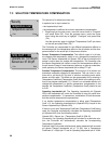
TEMPERATURE COMPENSATION CIRCUIT
Troubleshooting Procedure
Use this procedure to diagnose problems in the tem-
perature compensation circuit or as directed by the
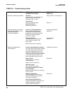
Troubleshooting Guide, Table 8-3. Refer to the appro-
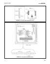
priate wiring diagram in Section 3.
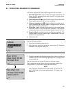
To check the sensor:
1. Check the resistance of the RTD element at the
end of the sensor lead. Do not include intercon-
necting wire. Disconnect the red lead and white
lead on the end of the sensor cable.
2. Check the resistance between the red and the white
leads. If values do not agree within ±1% of those
shown below, replace the sensor (see Step 4).
3.
Disconnect sensor leads from interconnecting wire
prior to measuring resistance. Values shown are
only accurate when measured at the end of the
cable directly attached to the sensor. Allow enough
time for the temperature compensation RTD
embedded in the sensor to stabilize to the sur-
rounding temperature. Temperature coefficient =
0.215 ohms per °F.
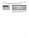
4. If the sensor is bad, you can replace the sensor, or
you can clear the fault by switching to manual tem-
perature compensation as a short-term solution.
Refer to Section 3.5 to program for manual tem-
perature compensation. If the temperature com-
pensator RTD in the sensor is bad, the displayed
temperature will be incorrect. Using manual tem-
perature compensation will remove all temperature
related faults.
OHMS AMBIENT TEMPERATURE
100.00 32°F/0°C
107.79 68°F/20°C
109.62 77°F/25°C
111.67 86°F/30°C
115.54 104°F/40°C
119.40 122°F/50°C
63