


22
MODEL 54e pH/ORP SECTION 5.0
SOFTWARE CONFIGURATION
SECTION 5.0
SOFTWARE CONFIGURATION
This section contains the following:
• An introduction to using the configuration process
• A List of Settings for the controller
• Step-by-step instructions and explanations for each parameter on the List
INTRODUCTION TO CONFIGURATION
The controller arrives from the factory configured and ready to operate as a pH controller. Refer to Appendix A for ORP meas-
urements.
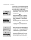
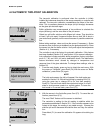
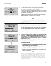
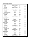
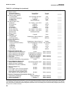
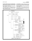
Figure 5-1 is an outline of the menu structure. Before attempting any changes refer to the parameter setup list shown in Table
5-1. This table presents a brief description and the possible options.
The factory setting is listed with a space for the user setting. It is recommended that the list be carefully reviewed before any
changes are made.
On initial configuration, it is recommended that the parameters be entered in the order shown on the worksheet. This will reduce
the chance of accidentally omitting a needed parameter.
ITEM CHOICES FACTORY SETTINGS USER SETTINGS
PROGRAM LEVEL (Sections 5.1 - 5.3)
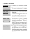
A. Alarm Setpoints (Section 5.2)
1. Alarm 1 (low action) 0 - 14 pH 0.00 pH _______
2. Alarm 2 (high action) 0 - 14 pH 14.00 pH _______
3. Alarm 3 (high action) 0 - 14 pH 14.00 pH _______
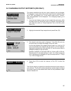
B. Output Setpoints (Section 5.1, 5.3)
1. Output 1: 4 mA 0 - 14 pH 0.00 pH _______
2. Output 1: 20 mA 0 - 14 pH 14.00 pH _______
3. Output 2: 4 mA –15 - 130°C 0.0°C _______
4. Output 2: 20 mA –15 - 130°C 100.0°C _______
CONFIGURE LEVEL (Sections 5.5-5.9)
A. Display (Section 5.5)
1. Measurement type pH/ORP/Redox pH _______
2. pH Resolution 0.01 pH/0.1 pH 0.01 pH
3. Temperature Units °C/°F °C _______
4. Output 1 Units mA/% (of full scale) mA _______
5. Output 2 Units mA/% (of full scale) mA _______
6. Language
English/Français/Español/Deutsch/Italiano
English _______
7. Main display lower left See Section 5.5 Alarm 1 Setpoint _______
8. Main display lower right See Section 5.5 Alarm 2 Setpoint _______
9. Display contrast 0-9 (9 darkest) 5 _______
10. Test Timeout On/Off On _______
11. Timeout Value 1-60 min 10 min _______
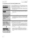
B. Outputs (Section 5.6)
1. Output 1 Control
(a) Output 1 Measurement Process/Temp/Glass Imp/Ref Imp Process (pH) _______
(b) Output1 Control Mode Normal/PID Normal _______
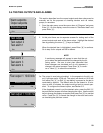
2a. Output 1 Setup (Normal)
(a) Current Range 4-20 mA/0-20 mA 4-20 mA _______
(b) Dampening 0-299 Sec 0 Sec _______
(c) Hold Mode Last value/Fixed value Last value _______
(d) Fixed Hold Value (if (c) Fixed) 0-22 mA 21 mA _______
(e) Fault value 0-22 mA 22 mA _______
TABLE 5-1. pH Settings List
Continued on the following page