


MODEL 54e pH/ORP SECTION 3.0
WIRING
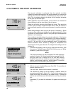
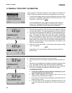
3.6 FINAL ELECTRICAL CHECK
When all wiring is completed, apply power to the con-
troller. Observe the controller for any questionable
behavior and remove power if you see a problem. With
the pH sensor in the process, the display will show a pH
value (though it may not be accurate).
CAUTION
To prevent unwanted chemical feed into the
process and to prevent injury to operating
personnel, disconnect the chemical feed
pump and other external devices until the
controller is checked out, programmed, and
calibrated.
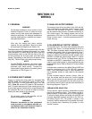
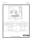
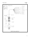
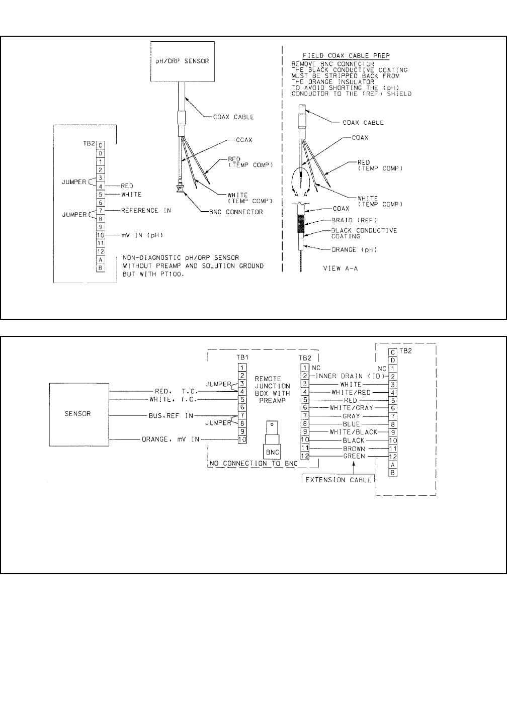
FIGURE 3-7. Wiring for Sensors Without Solution Grounds to a Junction Box (Models 389-02-54, 396-54, 399-09)
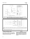
NOTES:
1. Interconnecting wire maximum length is 500 ft. Use PN 9200273 (no substitutes). Shields must be insulated from each other at all
cable ends. Connect to junction box as shown.
2. If distance to controller is short, the junction box is not required. Connect sensor leads directly to controller.
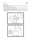
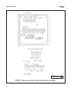
FIGURE 3-6. Wiring for Sensors Without Solution Grounds Directly to Analyzer (Models 389-02-54,
396-54, 397-54, 399-09). For wiring to a junction box, see Figure 3-7.
12