


64
MODEL 54e pH/ORP SECTION 8.0
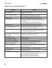
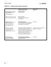
TROUBLESHOOTING
PREAMPLIFIER TROUBLESHOOTING
PROCEDURE
Use this procedure when diagnosing the circuit which
carries the signal from the sensor. There are 3 sepa-
rate procedures, depending on where the preamplifi-
er is located.
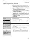
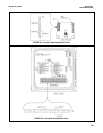
A. Preamp in a junction box (Figure 8-2)
1. Verify that the controller's preamp switch is in the
sensor/J box position (see Figure 2-5).
2. Remove the cover of the junction box.
3. Disconnect the BNC adapter or remove leads
from TB1-7 and TB1-10 (whichever is connect-
ed).
4. Install a jumper between 7 and 10, 3 and 4, and
7 and 8 (see Figure 8-2).
5. The controller should now read approximately
7 pH.
NOTE
If the controller has been calibrated with a
large zero offset, the pH may not be close
to 7. In this case, standardize the con-
troller at 7. (Section 3.4).
6. If the controller does not read correctly (after
standardizing, if necessary), go to step B.
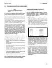
B. Controller preamp check (Figure 8-3)
1. Disconnect all sensor wiring from the controller
at TB2.
2. Verify that the preamp location switch is in the
analyzer position, and that temperature compen-
sation is set to manual at 25°C or 77°F (see
Section 3.5).
3. Jumper TB2-3 to TB2-4 and TB2-7 to TB2-8.
4. Jumper TB2-7 to TB2-10 to simulate 7 pH.
5. The controller should now read 7 pH (or 0 mV in
ORP mode).
NOTE
If the controller has been calibrated with a
large zero offset, the pH may not be close
to 7. In this case, standardize the con-
troller at 7. (Section 3.4).
6. If the controller does not read correctly (after
standardizing, if necessary), replace the con-
troller.
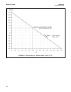
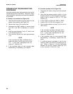
7. If a millivolt source is available, it can be con-
nected to TB2-7 and TB2-10 to simulate pH val-
ues. Refer to Figure 8-1 for the relationship
between mV and pH, sample values are +172
mV for 4 pH and -172 mV for 10 pH.