


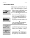
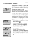
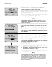
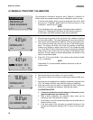
MODEL 54e pH/ORP SECTION 3.0
WIRING
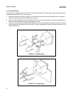
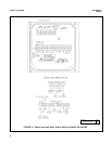
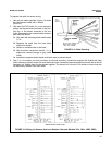
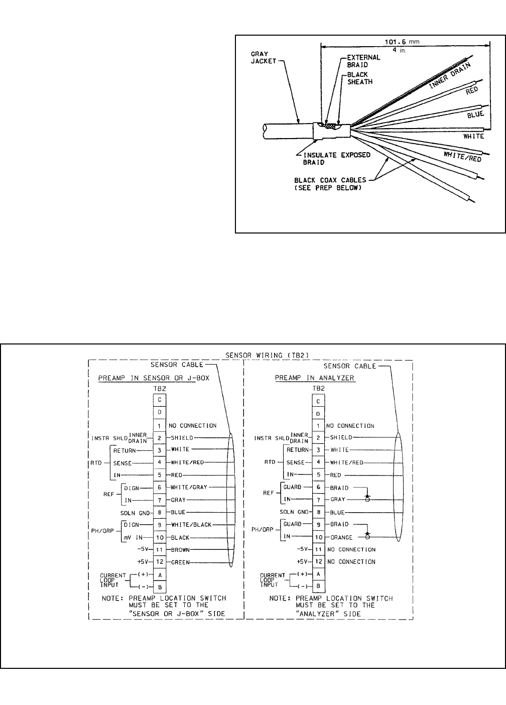
To prepare the cable for sensor wiring:
1. Use only the cable specified. Figure 3-4 shows
the 10 conductor cable with 3 shields
(9200273).
2. Strip back the PVC jacket 4 in. or far enough to
access the eleven screw terminals in the junc-
tion box, or the eleven terminals in the con-
troller. Separate the two coaxial cables and pre-
pare each as follows:
2a. Strip back the insulating black sheath about
1½ in.
2b. Separate the braid from the inner black
conductive sheath.
2c. Solder an insulated wire to the braid.
2d. Strip the black conductive sheath 1 in. to
expose the colored (orange or gray) cable
inside.
2e. Insulate the exposed black sheath and braid area to prevent shorts.
3. Strip ¼ in. of insulation on each conductor for terminal mounting. Insulate the exposed foil shields with heat
shrink sleeves or electrical tape. Be sure that heat shrink overlaps the exposed metal end where the foil shield
has been cut. Shields must not be shorted together. The sensor will not work if foil shields or drain wires are
not electrically isolated from each other.
FIGURE 3-4. Cable Dressing
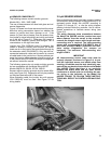
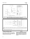
FIGURE 3-5. Wiring for Sensors that have Solution Grounds (Models 381+, 385+, 396P, 396R)
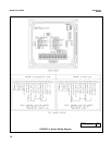
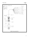
INSIDE FRONT PANEL VIEW
11