


15
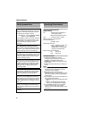
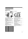
VN-V686WPBU
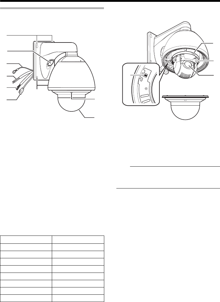
A
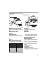
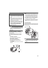
Camera securing hole (4 locations)
This hole is used for mounting the camera on the
wall.
B Cable connecting hole, cap
Remove the cap and pull out the cables from this
hole for connection.
(A Page 27)
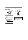
C Fall Prevention Wire
Connects the camera to the wall. Secure the
camera tightly to the anchor bolts used to mount
the fall prevention wire on the wall.
(A Page 28)
D AC 24 V Power Cable
This connects the camera to AC 24 V power. (A
Page 30)
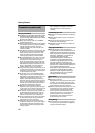
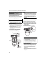
E Alarm Input/Alarm Output Cable (x8)
This cable is for alarm input and alarm output.
(A Page 25)
F LAN Cable
This connects the unit to the network.
(A Page 24)
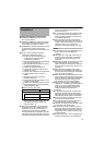
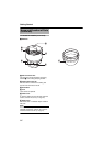
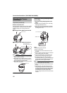
G Dome Cover
The dome cover is a delicate object. Handle it
with care.
Note:
● It is covered with a protective sheet during
shipment. Do not remove this sheet until
installation is complete.
H Dome Cover Fixing Screws (x4)
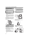
I Heater ON/OFF Switch
This is the automatic control ON/OFF switch of
the built-in heater.
The built-in heater prevents the dome cover from
fogging up and snow or frost from attaching to
the dome cover. When installing the heater at an
unrequired location, turn off the switch of the
heater. It is usually set to ON.
(A Page 26)
J Lens
Lens cannot be replaced.
K Front Mask
L [MAC address] indication
The MAC address is a unique physical address
of the product. This address cannot be altered.
A
H
B
C
D
E
G
A
F
Ⅵ Front side
L
K
J
I
Ⅵ Inner structure of
the camera
Cable color Signal Name
Brown Input 1
Red Input 1 COM
Orange Input 2
Yellow Input 2 COM
Green Output 1
Blue Output 1 COM
Purple Output 2
Gray Output 2 COM