


25
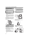
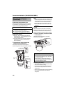
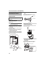
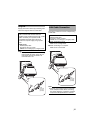
Connect the alarm signal cable to external
devices, such as a sensor or buzzer.
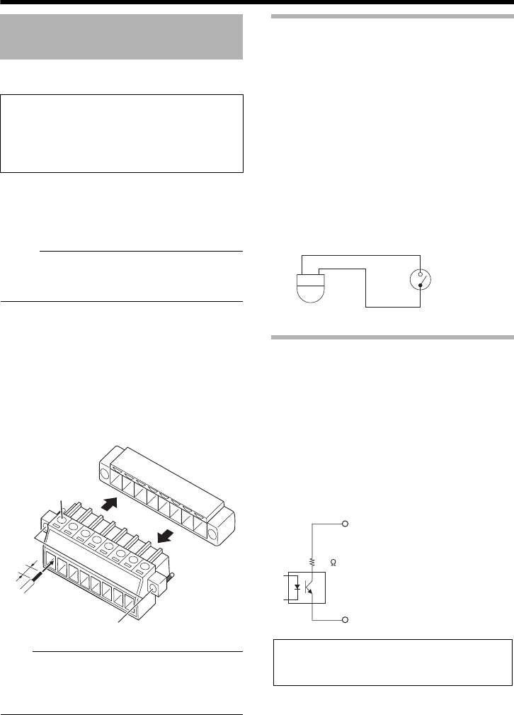
A Loosen screws on both sides of the
terminal block with a flathead screwdriver
and remove the terminal block as shown
in the diagram below.
M
emo:
● Inserting the tip of the screwdriver into the slit
of the terminal block will remove the terminal
block easily.
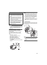
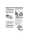
B Peel off about 4 mm of the alarm signal
cable covering and insert into the
terminal.
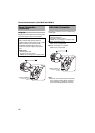
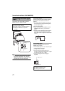
C Turn the screws at the side and secure the
alarm signal cable.
D When the alarm signal cable is secured,
return the terminal block that was
removed in A to its original position.
Note:
● Noises from an external source may cause
the camera to malfunction even when the
cable used is within 50 m. In this case, move
the cable away from the noise source.
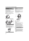
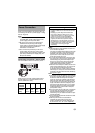
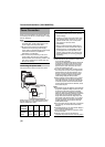
Alarm input signal
Connects to sensors such as infrared sensors,
door sensors, metal sensors and manual
switches.
● To prevent noise from entering the internal
circuit, supply non-voltage contact signal to
the alarm input signal.
● Do not supply voltage.
● When the contact is short (MAKE) or open
(BREAK) on the menu, you can set it to
Alarm.
● Supply such that the alarm signal continues
for at least more than 500 ms. The alarm
signal may not be recognized if it is less than
500 ms.
Alarm output signal
Connect to alarm devices such as alarm,
indicator, light or buzzer.
●
Alarm output signal is an open collector output
insulated with photo coupler.
●
During an alarm, it is ON.
●
As this terminal is polarized, be sure to
connect it such that the voltage of the + output
is higher than that of the – output.
●
It will be damaged if reverse voltage is
supplied.
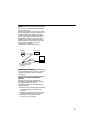
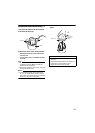
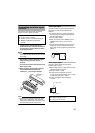
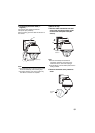
Connecting the alarm signal
terminal
Cable to use
● Length of 50 m or shorter
● UL1007, UL1015 or equivalent products
● AWG#22 to AWG#18 or equivalent
products
4 mm
A
B
C
A
D
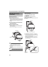
Alarm signal
terminal
IN
COM
OUTPUT
COM
22
Rating:
Max. applied voltage: DC 20 V
Max. driving current: 25 mA