


20
Connection/Installation (VN-V685U/VN-V686BU)
Preparation (continued)
8
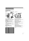
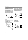
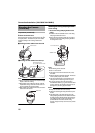
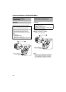
Mount the terminal cover
Return the terminal cover that was removed in step
3
to
its original position. The direction to pull out the cables
changes according to the mounting method of the
camera.
Note:
●
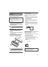
Be sure to mount the terminal cover to prevent foreign
objects or dust from entering.
●
When pulling out the cables from the top, make the
fall prevention wire go under the terminal cover and
pull it out together with the other cables.
●
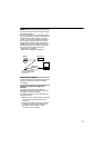
When pulling out the cables from the side, remove the
cable cover of the camera.
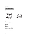
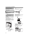
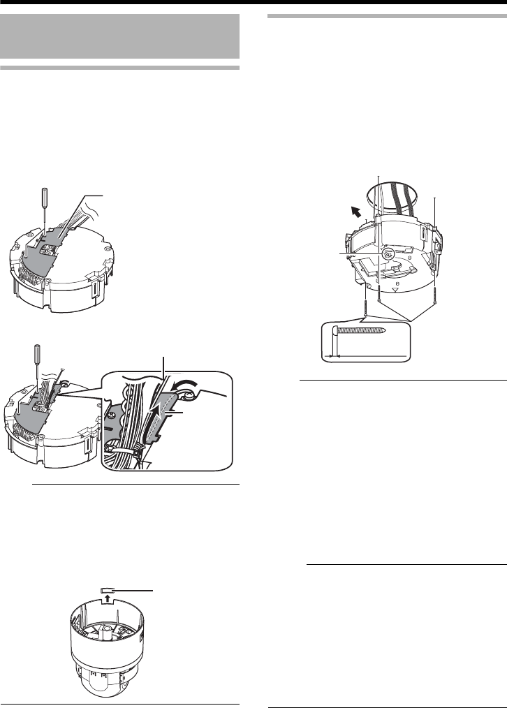
Mounting the ceiling clamping bracket
to the ceiling
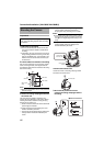
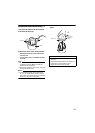
1
Secure the ceiling clamping bracket to the
ceiling
●
Install such that the
A
D
FRONT mark
B
of the ceiling
clamping bracket faces the front.
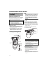
●
Ensure that the connection cables are not caught in
between and secure the ceiling clamping bracket to
the ceiling with 3 screws.
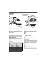
Note:
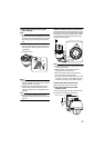
●
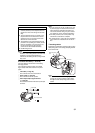
Use M4 fixing screws and bolts.
●
Use
R
4.1 wood screws.
●
The length of the screws should be 25 mm (1inch)
and above.
●
Place the product horizontally and install. The camera
will not operate properly if it is slanted.
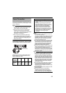
●
The screw head should be 5 mm and below. If the
ceiling structure is metal, image noise may occur.
●
Do not use screws for which the screw head is
embedded after fastening. (e.g. flat countersunk head
screws). Otherwise, the insulating resin part may be
damaged, thus preventing proper insulation.
M
emo:
●
Always use 3 screws and mount securely.
●
Tighten the screws again during maintenance just to
be safe.
●
The plastic parts on the ceiling fixing holes of the
ceiling clamping bracket act as an insulation between
the ceiling clamping bracket and the ceiling structure.
If the ceiling structure is metal and insulation is not
provided between the camera and the ceiling
structure, image noise may occur. Be sure to provide
insulation.
Mounting the Camera
(continued)
Ⅵ Pulling out the cables from the top
Terminal cover
Fall Prevention Wire
(To go under the terminal co
v
Ⅵ Pulling out the cables from the side
Te r mi n al
cover
Cable cover
Screws
DFRONT mark
Front of the camera
5 mm (3/16
inch) and below