


19
M
emo:
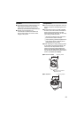
● The wire should be insulated from the ceiling
structure. If the ceiling structure is metal and
insulation is not provided between the
camera and the ceiling structure, image noise
may occur.
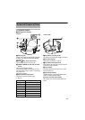
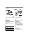
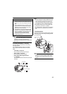
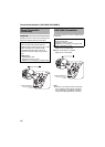
6 Connect the cable (A
23 to 25)
Connect cables to the terminal of the ceiling
clamping bracket.
The connection cables consist of the alarm
signal cable, LAN cable and AC 24 V power
cable.
A LAN cable (A Page 24)
This connects the unit to the network.
B Power cable (A Page 23)
This connects to AC 24 V power.
C Alarm input/output signal terminal
(A Page 25)
This connects to devices with alarm input/output
terminals.
Note:
● Do not connect an AC 24 V cable to AC 110
V power supply. The camera internal circuit
will be damaged. Should that happens, do
not use the camera. Bring it to your nearest
JVC dealer for repair. (charged separately)
● For safety reasons, turn on the power only
after all the connection is complete.
● To supply AC 24 V, use an AC 24 V supplying
power unit that is insulated from AC 100 V
line.
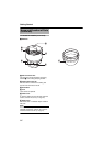
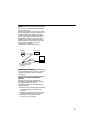
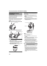
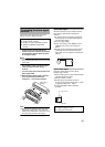
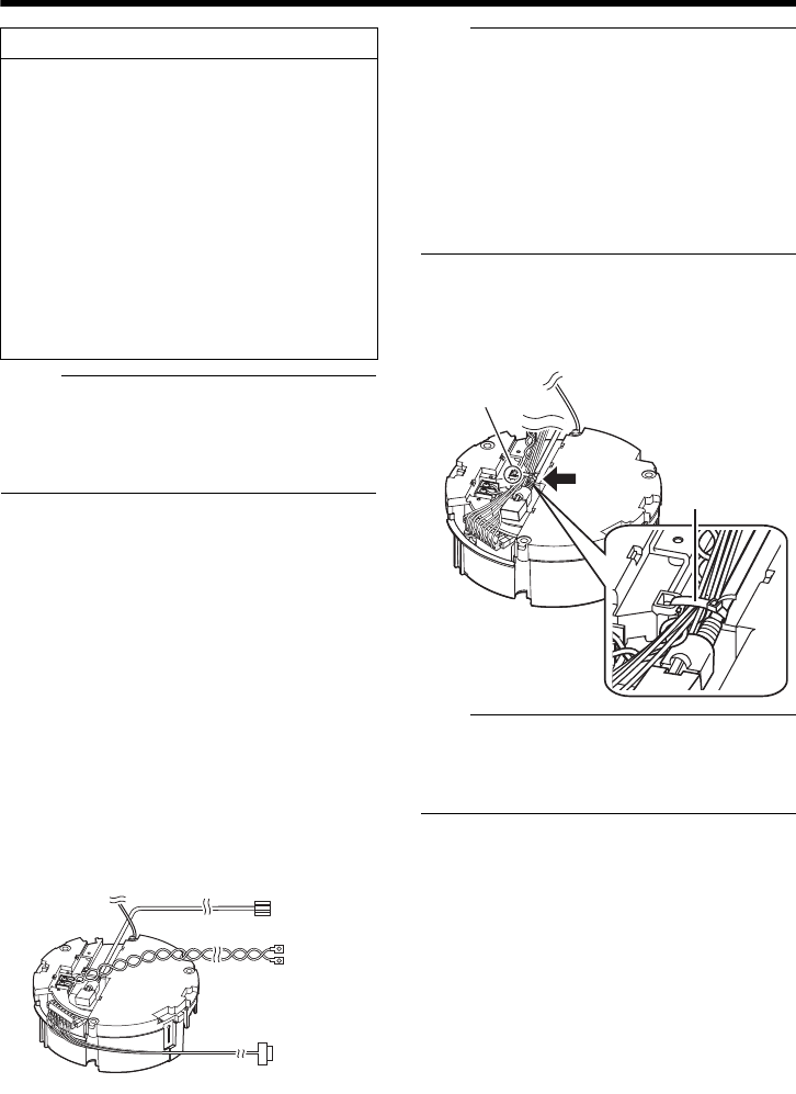
7 Handling cables
Thread the provided wire clamp through the wire
clamp fixing hole of the ceiling clamping bracket
to tie all the wires.
Note:
● To prevent the cables from tangling and
coming off, be sure to thread a wire clamp
through the wire clamp fixing hole to tie the
cables.
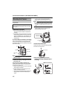
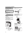
Caution
●
Take note of the length, strength, pull and
material (insulation) of the fall prevention wire
and use one with a wire strength of more than
20k
g
.
●
The inner diameter of the ring section of the
fall prevention wire mounted on the camera
should be
R
4 mm to
R
5.5 mm and the outer
diameter be
R
9 mm and below.
●
The thickness of the screw head and the fall
prevention wire (including the washer) should
be 6 mm and below. If it is more than 6 mm,
the screw will touch the ceiling and the
camera cannot be installed horizontally.
●
Use M4 fixing screws.
A
B
C
Alarm signal cable
Power cable
LAN Cable
Tie here
Wire clamp fixing
hole
Wire clamp