96
Chapter 6 Maintenance and inspections (continued)
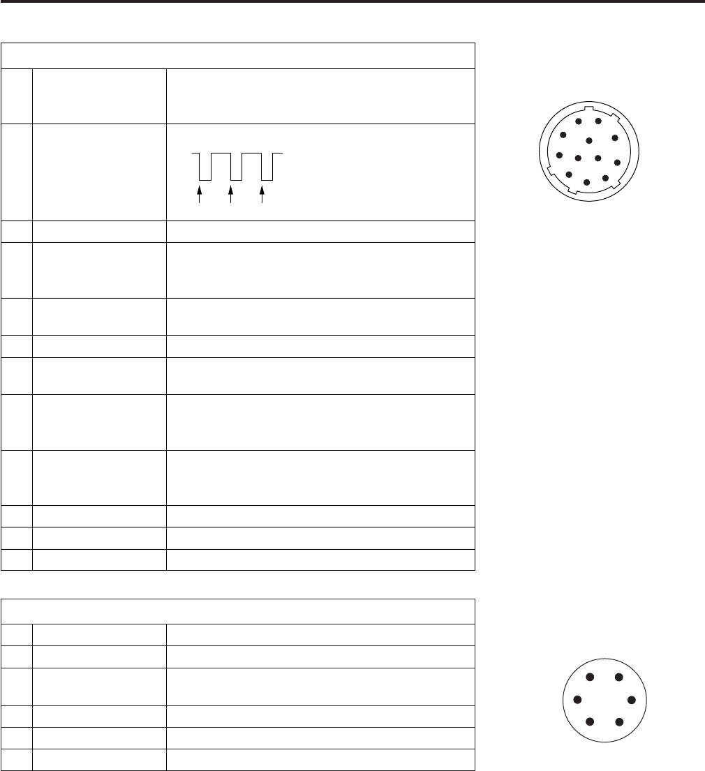
GPS
1 GPS TXA Transmission data from the GPS unit to the camera
2 GPS RXA Transmission data from the camera to the GPS unit
4 REC START SW Control signals of REC start/stop
5 GPS VCC Power supply connector for the GPS unit (DC+3.3 V)
6 GPS GND GND
3 GPS VBAT Backup power supply connector for the GPS unit
(DC+3.3 V)
Matsushita part number K1AY106J0001
Maker part number
HR10A-7R-6SC(73)
(Hirose Denki)
1
2
4
5
6
3
Matsushita part number K1AY112JA001
Maker part number
HR10A-10R-12SC(71)
(Hirose Denki)
1
2
4
5
6
3
7
8
9
10
11
12
LENS
1 RET-SW ON/OFF of the return video
RETURN ON: GND
RETURN OFF: OPEN
2 REC-START/STOP Control for recording start/stop
4 IRIS-AUTO ON/OFF of the forced iris servo
SERVO ON: +5 V ±0.5 V
SERVO OFF: OPEN
5 IRIS-CONT Control output for the lens iris
F2.8: –6.2 V, F16: +3.4 V, CLOSE: +2.5 V
6 UNREG-12V +12V power supply for the lens (Max. 1.5 A)
7 IRIS-POSI Iris position signals
3.4 V (F16) to +6.2 V (F2.8)
8 IRIS-G-MAX IRIS REMOTE/LOCAL (AUTO) signals
REMOTE: +5 V ±0.5 V
LOCAL (AUTO):GND
9 EXT-POSI ON/OFF of the built-in extender
EXTENDER ON: GND
EXTENDER OFF: OPEN
10 ZOOM-POSI Zoom position signals
11 FOCUS-POSI Focus position signals
12 SPARE Standby (not used)
3 GND GND
START STOP START
+5 V
0 V


