


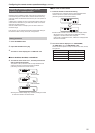
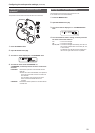
32
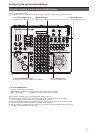
Setting the functions for when the unit is linked with the switcher
Set the functions that can be used when there is a link between the unit
and switcher.
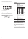
Each of the functions needs to be set in advance in SW FUNCTION
menu [42] and SW INPUT menu [43].
⇒ “Registering the camera numbers that will correspond to the image
inputs of the switcher” (page 31)
⇒ “Enabling or disabling the function for linking with the switcher”
(page 31)
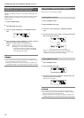
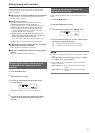
BUSCONT function
Select the bus material of the switcher from the unit.
When the BUSCONT function is enabled, the bus material of the
switcher can be selected in conjunction with camera selection on the
unit.
z When the link setting of a camera number is changed with
AUTO IP menu [37], SWAP IP menu [38], or MANUAL IP menu
[39] or a camera number corresponding to an image input of
the switcher is changed with SW INPUT menu [43], the bus
material of the switcher will not be changed immediately even
if the BUSCONT function is enabled. Press one of the camera
selection buttons [CAMERA SELECT/GROUP SELECT] to make
a selection again.
Note
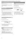
Enabling or disabling the BUSCONT function
1.
Press the MENU button.
2.
Open SW FUNCTION menu [42].
3.
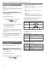
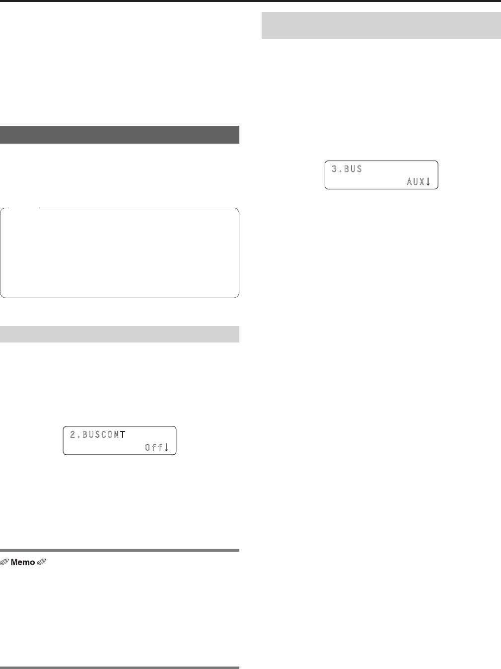
Turn the F1 dial to display the “2. BUSCONT” item.
2.BUSCONT
Off
4.
Turn the F2 dial to select “On” or “Off”, and then press
the F2 dial to confirm the selection.
On : Enables the BUSCONT function.
Off : Disables the BUSCONT function.
z Enabling and disabling the BUSCONT function can be assigned to a
USER button.
Open USER BUTTON menu [35], display one of the “1. USER1”
to “8. USER8” items, and set “BUSCONT”.
z When the USER button with “BUSCONT” assigned is pressed, the
operation is as follows.
Button indicator on : Enables the BUSCONT function.
Button indicator off : Disables the BUSCONT function.
Setting the switcher bus to control with the BUSCONT
function
When the BUSCONT function is enabled, you can set the switcher
bus to control with a camera selection button [CAMERA SELECT/
GROUP SELECT] on the unit.
1.
Press the MENU button.
2.
Open SW FUNCTION menu [42].
3.
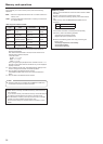
Turn the F1 dial to display the “3. BUS” item.
3.BUS
AUX
4.
Turn the F2 dial to select a setting, and then press the
F2 dial to confirm the setting.
AUX : The AUX bus of the switcher is the control target.
PVW : The PVW bus of the switcher is the control target.
PinP : The PinP bus of the switcher is the control target.
KEY : The KEY bus of the switcher is the control target.