


43
Control interface for external devices
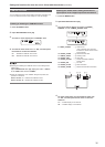
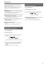
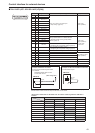
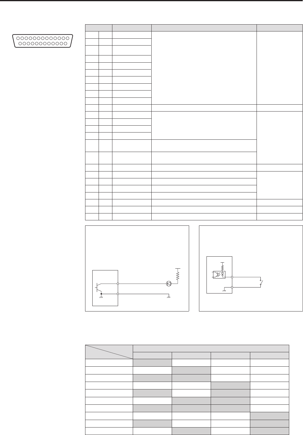
TALLY/GPI (JST: JBY‑25S‑1A3F(LF)(SN))
13 1
25
14
Pin number Signal name Description of signal Operation
1 TALLY IN 1
TALLY IN1 to TALLY IN10 tally inputs
⇒ “Tally settings” (page 39)
Contact input
(Status operation)
14 TALLY IN 2
2 TALLY IN 3
15 TALLY IN 4
3 TALLY IN 5
16 TALLY IN 6
4 TALLY IN 7
17 TALLY IN 8
5 TALLY IN 9
18 TALLY IN 10
6 GND GND
19 GPI IN 1
Calling of PMEM GROUP1 to PMEM GROUP4
⇒ “Operating preset memory groups (PMEM
GROUP)” (page 16)
Contact input
(Trigger operation)
z Trigger width
30 msec
7 GPI IN 2
20 GPI IN 3
8 GPI IN 4
21 GPI IN 5
Control of the ENABLE BUTTON settings
⇒ “Configuring the unit operation settings” (page 27)
9 GPI IN 6
Control of MENU CONTROL settings
⇒ “Configuring the unit operation settings” (page 27)
22 GND GND
10 GPI OUT 1 Remote camera selection 0
*
Open collector output
(Status operation)
23 GPI OUT 2 Remote camera selection 1
*
11 GPI OUT 3 Remote camera selection 2
*
24 GPI OUT 4 Remote camera selection 3
*
12 GPI OUT 5 Alarm
25 GND GND
13 NC
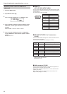
GND
GPI OUT
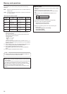
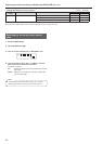
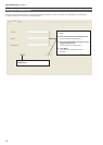
Example of GPI OUT connection
Ensure that the conditions given below
are satisfied.
Withstand voltage: Max. 24 V DC
Current: Max. 50 mA
AW‑RP120
(Max. current 50 mA)
(Max. voltage 24 V)
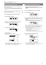
Example of TALLY IN and GPI IN connections
Provide contact inputs.
GND
GPI IN
TALLY IN
+3.3 V
AW‑RP120
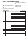
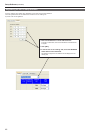
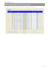
For the cameras registered to the “1. CAM OUT1” to “10. CAM OUT10” items in GPI OUT menu [45], the
selection states on the unit can be output to GPI OUT1 to GPI OUT4.
<Output states of GPI OUT1 to GPI OUT4 when the camera number registered to CAM OUT is
selected>
Output of GPI OUT1 to GPI OUT4
GPI OUT1 GPI OUT2 GPI OUT3 GPI OUT4
CAM OUT1 On Off Off Off
CAM OUT2 Off On Off Off
CAM OUT3 On On Off Off
CAM OUT4 Off Off On Off
CAM OUT5 On Off On Off
CAM OUT6 Off On On Off
CAM OUT7 On On On Off
CAM OUT8 Off Off Off On
CAM OUT9 On Off Off On
CAM OUT10 Off On Off On